

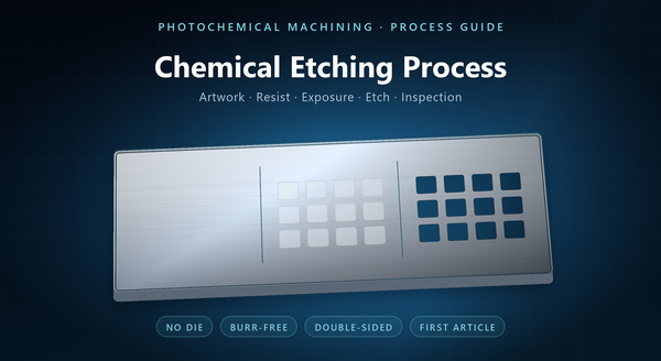
chemical etching guide
A chemical etching process guide is really a guide to control: every step either defines the pattern or narrows the tolerance the shop can hold. Photo chemical etching uses a photoresist mask and an etchant to dissolve metal, so it produces burr-free parts without a die, and the precision comes from the artwork, the exposure and the etch time rather than from a cutting tool. In a chain like this, a defect created at the artwork stage cannot be corrected in the etch tank, and a drift in the tank cannot be recovered at inspection. The eight sections below follow that chain from the digital file to the packed part.
1. Artwork and Phototool: Compensating for Etch Factor
The chain starts in the CAD file. The etchant removes metal downward and sideways at the same time, so a slot drawn at nominal width comes out wider, a web comes out thinner, and a hole comes out larger than the drawing. Etch factor describes the relationship between the depth of cut and the sideways undercut, and it converts a finished dimension back into an artwork dimension.
Compensation is applied before anything is imaged. Outlines are offset for the sideways removal, holes are adjusted in the opposite direction, and the correction is reviewed feature by feature rather than once per panel. Panel layout matters as much as the offset: parts are arrayed with consistent spacing, the finest features stay away from the panel edge where flow is least stable, and the panel outline carries the tooling marks the rest of the line will use.
The phototool is then imaged from the compensated artwork, and its own accuracy enters the tolerance stack. A film that is slightly out of scale, or a panel punched slightly off, shifts every feature at once. A change to the artwork is the cheapest change in the process.
2. Cleaning and Resist Lamination
Etching only works on metal the resist actually covers, so the front end is a cleanliness problem before it is a chemistry problem. Sheet arrives with oil, oxide, dust and handling marks, any of which can stop the resist bonding. The sheet is degreased, rinsed and dried, then inspected before lamination rather than after exposure, when the evidence is already buried.
Resist is applied as a dry film or a liquid coating. Dry film is laminated with heat and pressure through rolls, and its two failure modes are trapped air and weak adhesion. A bubble becomes a pinhole in the finished part; a weakly bonded edge lets etchant creep under the resist and leaves a ragged line.
Resist thickness sets how long the mask survives in the tank and how fine a feature it can hold. Thicker resist is more durable but resolves less detail; thinner resist holds fine lines but erodes sooner. Handling after lamination matters too: a fingerprint or scratch in the resist becomes a defect in metal.
3. Exposure and Development
The laminated panel is exposed through the phototool under ultraviolet light. Dose is the product of intensity and time, and both are controlled, because the resist needs a minimum dose to cross-link and become insoluble. Under-exposure leaves the image areas soft, and the developer attacks lines that should survive. Over-exposure drives light under the opaque features of the phototool and rounds the sidewalls, which costs fine detail.
Development removes the unexposed resist and leaves the pattern to be etched. Developer concentration, temperature, time and spray pressure all change the result, and the endpoint is when the last unexposed resist clears, not a fixed time. A panel developed too long loses adhesion at the pattern edges; one developed too short leaves a film that blocks the etchant and produces a shallow feature.
The check that matters happens before the metal is gone. Pattern integrity, line width and resist defects are visible after development and invisible after etching, so development is a quality gate, not only a process step.
4. Etching Chemistry and Undercut Control
The etchant is selected to match the alloy, and the operating point is set by time, temperature, concentration and how the chemistry reaches the surface. Undercut grows with time: the longer a panel stays in the tank, the further the etchant works sideways under the resist. Etch factor is therefore not a material constant. It is a result of the operating point, and it changes with the bath.
Bath control is continuous. Dissolved metal accumulates as panels are processed, and the etch rate falls unless the chemistry is analysed and replenished. Spray pressure and nozzle pattern decide whether fresh etchant reaches every feature at the same rate; a blind spot leaves a region under-etched while the rest is correct. Etch rate is measured on a coupon from the same lot before production, so time comes from data, not from the previous job.
Ending the etch is its own decision. Over-etching opens dimensions and thins webs; stopping early leaves metal bridges that have to be removed by hand. The window between the two is narrow on fine features, which is why the coupon, the bath record and the operator’s inspection feed the same decision.
5. Resist Stripping and Post-Etch Finishing
Once the geometry is complete, the resist has done its job and has to come off completely. Stripping lifts the resist without attacking the metal; the panel is then rinsed and dried. Incomplete stripping leaves patches that mask the surface and fail a cleanliness check. The rinse matters as much, because residual stripper keeps working after the part leaves the tank.
Post-etch finishing depends on the alloy and the application. Parts are cleaned, checked for handling damage and, where the specification calls for it, given a surface treatment such as passivation. The etched edge differs from a sheared or machined edge: it is smooth, burr-free and slightly tapered by the undercut, and that taper is normal rather than a defect.
This is also where the delivery format is fixed. Parts that ship on the frame stay attached through stripping, cleaning and packing; parts that ship loose are separated here, which puts break quality and the risk of loss in the same step. Deciding that later usually means deciding it twice.
6. Inspection and the First-Article Baseline
Inspection closes the loop, and it should measure the features the process actually controls. Dimensions, feature size, undercut, flatness and surface condition are checked against the drawing. Undercut is most often skipped because it needs a coupon or cross-section, yet it explains every other deviation.
The first article establishes the baseline. The etch factor recorded there is the number the next batch is planned against, and it should be stored with the alloy lot, the resist lot, the bath condition and the etch time that produced it. Without them it cannot be reproduced, and the baseline becomes a memory of one good day.
Inspection also decides what “good” means at the edge. A witness mark on a hidden face and the same mark on a sealing face are not the same defect, so limits are written per edge rather than as one number for the whole part. That distinction prevents arguments at incoming inspection and gives the supplier a target it can hold.
7. Double-Sided Registration and Batch Consistency
Through-cut parts are etched from both faces, and the two patterns have to line up. Registration error appears as a step on the cut wall, a hole that is off centre, or a thin witness line where the two etches fail to meet. Panel and phototool are therefore located from the same tooling features, and registration is checked on the panel, not assumed from the fixture.
Registration tolerance has to be consistent with feature size. A small offset that is invisible on a large opening can close a narrow slot or shift a critical edge, so the tightest features set the requirement for the whole panel. Double-sided work also doubles the process variables: both exposures and both development steps must match.
Batch consistency is a record-keeping problem as much as a chemistry problem. The same artwork, alloy lot, resist lot, bath control and operating procedure give the same result; change one and the first article should be repeated. Traceability makes that possible, and turns a complaint into a correctable cause.
8. Ordering the Job and Common Mistakes
A clean order removes most of the risk before the first panel is etched. Supply a CAD file the shop can open without translation, the alloy and temper, the thickness and its tolerance, the critical features and the finish the part needs. State the quantity, the delivery format and whether the parts ship on the frame.
Two questions are worth asking every supplier. How is etch factor compensated in the artwork, and how is the first article verified? The answers separate a controlled process from a hopeful one. If the drawing has stepped depths or half-etched areas, confirm how many masking passes are needed, because those features come from repeated cycles, not a single etch.
The common mistakes are consistent. Artwork is issued at nominal dimensions with no compensation. A tolerance is quoted tighter than the etch factor can support. A critical feature sits at the panel edge. The alloy or temper is left unspecified. No first article is agreed, so the first delivery becomes the negotiation. Each is cheap to fix on paper and expensive to fix in metal.
