

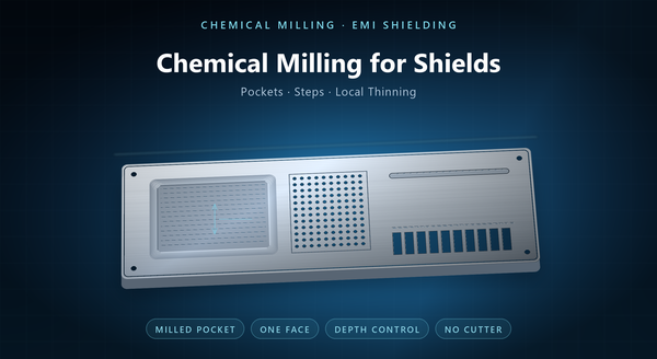
chemical milling shielding parts
Chemical milling removes metal to a controlled depth across an area instead of cutting a shape out of it. On an EMI shield that difference matters. A lid can carry a pocket that clears a tall component, a wall can be thinned where weight matters and contact does not, and a step can tune the height of an enclosure, all without a cutter touching the part and without disturbing the face that has to sit flat on the board. The process is a close relative of the through-etching used for apertures and outlines, but the tooling, the rules and the failure modes are different. This page sets out the difference.
1. Milling Is Depth; Etching Is Outline
A through-etch removes all the metal inside a shape, from both faces, and its quality is judged by the edge: aperture size, wall profile, position. Chemical milling removes part of the thickness over an area, usually from one face, and its quality is judged by the floor: how deep, how flat, and how the slope at the mask edge behaves.
The tooling follows from that. Through-etching needs a phototool with fine features and registration between two images. Milling needs a mask that can survive a long immersion and be stripped cleanly, which is often a peelable elastomeric maskant for large areas and a photoresist where the pocket outline has fine detail.
The economics differ too. Milling removes far more metal per part and takes far longer in the tank, so it is used where the geometry demands it rather than as a general-purpose alternative to forming. That is why the two are quoted and inspected separately; a shop that treats milling as a variant of etching will under-estimate the tank time and over-promise the floor.
2. Where Milling Earns Its Place on a Shield
Four duties recur.
Component clearance is the common one. A shield lid that must sit close to the board often has to clear a connector, an inductor or a can, and a milled pocket provides that clearance while keeping the rest of the lid thin.
Local thinning follows. Where a shield wall is thicker than the load requires, milling removes the excess without touching the contact face, which is the face that must stay flat and conductive.
Stepped cavities are the third. A step in the floor of a lid changes the internal height without changing the outside envelope, which is useful when a housing has already been tooled.
Recesses for gaskets and labels are the fourth: a shallow milled pocket locates a conductive gasket or protects a printed label from wear.
In all four the electrical function is unchanged. At these depths the shielding performance of the wall is set by its continuity rather than by a fraction of a millimetre of thickness, so milling is a mechanical decision.
3. How Depth Is Controlled
Depth is rate multiplied by time, and both drift. Rate depends on the etchant, its temperature, its metal loading and the agitation reaching the pocket floor; time is what the operator sets. A pocket that is deeper than its neighbours usually means slower local flow rather than a different mask.
Large areas are harder than small ones. A wide pocket holds a boundary layer of depleted etchant at its centre, so the floor etches more slowly there unless the bath is agitated deliberately, and the panel is oriented so the pocket drains and refreshes.
Stepped depths are produced by re-masking and etching again, or by masking in stages. Each step adds a registration and a measurement, which is why a two-step pocket costs noticeably more than a single depth.
Measurement is by depth gauge, by a step-height instrument, or by a coupon milled with the lot. The customer’s drawing should say which depth is critical and how it will be checked, because a floor that is flat to one tolerance and deep to another is two different requirements.
4. Maskant, Artwork and Registration
The mask is the whole tool. For a coarse pocket, a peelable maskant is applied, scribed to the pocket outline and peeled, leaving bare metal only where the pocket will be. For fine detail, a photoresist is imaged and developed as in through-etching.
Milling one face leaves the other face untouched, which is often the point: the outside of a lid stays smooth and the inside carries the pocket. Where both faces are milled, the two masks must register, and the registration error shows up as a wall whose thickness varies around the pocket.
Two practical rules follow. Keep milled pockets away from through-features that will be etched later, or mill first and etch after, so the second operation does not have to find an edge that has already moved. And give the mask outline a land width, because the etchant undercuts the mask and the slope it leaves is proportional to the depth. Where the pocket is large and the part is thin, the mask can bridge the area and trap etchant, so the layout should include drain paths rather than covering the panel edge to edge.
5. Design Rules for Milled Shields
Remaining wall comes first. A pocket is a place where the part is thinner, so the drawing should state the minimum remaining thickness rather than only the depth, and the two should agree with the load the shield carries.
Corners should be radiused. A sharp internal corner in a mask is hard to hold and etches unevenly, and in a thin shield it also concentrates stress.
The slope at the mask edge needs room. Because undercut grows with depth, a deep pocket consumes a band of material around its outline, and that band must not reach a sealing land, a bend line or a contact area.
Floor flatness is a separate callout from depth. A large pocket will not be as flat as a machined one, and asking for machined flatness on an etched floor is asking for a different process.
Finally, think about the bend. A pocket across a fold line changes how the fold behaves, so either keep the pocket clear of the bend or accept a wider bend radius.
6. Combining Milling with Through-Etching
Most shield parts that need a pocket also need apertures, fingers or mounting holes, and the two operations can run on the same part.
The usual sequence is mill first, then through-etch, because the through-etch defines the part outline and the fine features last. The alternative, etching the outline first and milling afterwards, works when the pocket has to be positioned relative to an edge that already exists.
Either way, the two operations must share a datum. If the pocket is located from the artwork of one operation and the apertures from another, the tolerance stack between them belongs on the drawing, not in the shop’s assumption. Settling that early is cheaper, because a pocket located from a second operation inherits that operation’s tolerance as well as its own.
Handling is the quiet cost. A milled pocket makes the panel less stiff, and a large thin area is easier to distort in rinsing and transport, so tabs and frame layout may need to change when a pocket is added.
7. Cost, and When Not to Mill
Milling adds a masking step, a long etch and a depth inspection, so it is rarely the cheap option. It earns its cost when the alternative is worse: machining a pocket into a thin shield leaves burrs on a contact face, and a machined floor can distort the part; assembling a spacer adds a part and a tolerance.
It loses when a simpler geometry would do. A thinner sheet with a formed rib often delivers the same stiffness as a milled wall, and a pocket that exists only to clear a component can sometimes be replaced by moving the component or changing the lid height.
The honest comparison is between finished-part cost and risk, not between removal rates. A milled pocket that causes a flatness problem at assembly has cost more than the machining it replaced.
8. Inspection and Order Notes
Inspection of a milled shield checks depth at several points across the pocket, floor flatness, remaining thickness, the slope band at the mask edge, and the absence of any breakthrough. A witness mark from the mask is normal and its acceptance should be agreed rather than discovered.
An order should state the base material and thickness, which face is milled, the pocket outline with its corner radii, the depth and its tolerance, the minimum remaining wall, the floor flatness limit and how it is measured, the land width that must survive, the finish, and whether through-features are etched in the same part.
The recurring mistakes are a depth with no remaining-wall minimum, a pocket outline that reaches a sealing land, an expectation of machined floor flatness, and a step depth specified without saying which of the two depths is the reference. A first article that records depth at five points and a flatness trace is worth more than a report that says the pocket was checked.
