

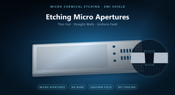
fine mesh etching EMI shield
Micro chemical etching is how an EMI shield gets a fine aperture field: hundreds of small openings across a thin panel, all formed at once by chemistry rather than one at a time by a beam. The distinction matters because the two processes fail differently. A drilled field varies with drill order and heat; an etched field varies with flow and dwell time. This page is about the etched side of that comparison: what sets the smallest feature, why thin foil behaves the way it does, how uniformity is held across a panel, and what a drawing has to state for a micro field to be reproducible.
1. What “Micro” Means in Etching
A feature is micro when its size approaches the thickness of the sheet being etched. At that point the etchant’s sideways travel is no longer a small correction to the downward cut; it is comparable to the feature itself, and the process stops behaving like a plotter and starts behaving like a diffusion problem.
In practice that means two regimes again. In thick sheet, a small feature is a narrow slot with a deep wall, and the limiting factor is how much etchant can reach the bottom. In thin foil, the wall is short, the sideways travel is a large fraction of the hole, and the limiting factor is how precisely the two-sided etch can be stopped and registered.
Shield vent fields in foil sit in the second regime. That is the regime this page addresses. It is also why a micro field cannot be designed by scaling a coarse one down: the rules change at the point where the two lengths meet.
2. What Sets the Smallest Feature
Four things, and they interact.
Resist resolution sets the floor on what the artwork can define. A phototool and a resist can carry detail finer than the chemistry will hold, so resist is rarely the limit once a shop is set up for fine work, but a coarse laminate will blunt an edge before the etchant does.
Etch factor — the ratio of sideways undercut to depth — sets how much the feature grows beyond the artwork. It depends on chemistry, temperature, agitation and how the panel sits in the tank. A higher etch factor means straighter walls and features closer to the drawn size; a lower one means the aperture widens and the ligament narrows.
Thickness sets the depth that has to be cut, and depth is what the undercut scales with. This is why the same artwork produces a different result at two gauges, and why a design that works at one thickness cannot be assumed at another.
Registration sets whether the two sides meet where they should. A fine field etched from both faces needs the two images aligned; when they are not, the aperture becomes a stepped hole rather than a straight one, and the effective open area changes.
3. Working with Thin Foil
Thin foil is where micro etching earns its place and where most handling problems live. The material is supplied in rolls or sheets, it wrinkles if it is not supported, and it will not stay flat through a wet process without help.
Lamination is the first control. The resist has to bond without trapping air, because a bubble becomes a pinhole in the finished field. Clean rooms are not required, but a dusty laminator is a slow way to scrap a panel.
Support is the second. Foil is usually etched in a frame or on a carrier, and the part stays attached to that frame by tabs until it is packed. The tab layout is a design decision, not a shop default: too few tabs and the part sags in the rinse, too many and the witness marks multiply.
Drying is the third. A wet foil panel that is dried unevenly will curl, and a curled panel does not measure flat. Flatness on a micro field is often more about drying than about etching.
4. Holding Uniformity Across the Panel
A dense field is a large area of metal removal, and the etchant near the surface is depleted as it works. Fresh chemistry reaches the centre of a large field more slowly than the edges, so a panel etched without deliberate flow comes out with apertures that vary from rim to centre.
Three levers control that. Agitation has to reach the field, not just the panel edge. The panel’s orientation in the tank decides whether spent etchant drains away or pools. And loading — how much metal is being dissolved per unit of bath — decides how fast the chemistry drifts during the run.
The practical consequence for a drawing is that open area and panel size are process variables, not just design choices. A field that covers most of a large panel is harder to hold uniform than the same field split across two smaller panels. Where the field is the dominant feature on the panel, splitting it is often cheaper than inspecting around the variation.
5. Tolerance, Measurement and Open Area
Micro fields are specified by three numbers: aperture with a tolerance, open area, and the minimum ligament. All three should appear on the drawing, because any two of them can be met while the third fails.
Aperture is measured optically at several positions and reported as a range. A single reading from the centre of the panel tells nothing about the rim, which is where the variation lives.
Open area is derived from aperture and pitch, or measured directly by optical scanning, and the two methods should agree within the tolerance. A field that passes on derived open area while failing a direct scan is usually a sign that the pitch drifted rather than the aperture.
Ligament is the one that fails quietly. It is not usually measured unless it is called out, and a field with apertures on nominal and ligaments below minimum will pass a diameter check and tear in handling.
6. Design Rules for Etched Micro Fields
Round every internal corner, for the same reason as anywhere else in etching: etchant pools in a sharp corner and the feature comes out under-cut there.
Keep the ligament proportionate to thickness. A web thinner than the foil is a web that will distort before it is inspected, and the finer the field, the more this bites.
Avoid isolated islands of metal inside a large opening. A small island has to be held by something, and in a fine field the holding feature is often thinner than the island itself.
Space the field away from the panel edge. The edge etches differently because the etchant approaches it from two directions, and a field that runs to the edge inherits that variation.
Put the tabs where a witness mark is acceptable, and keep them out of the field. A tab inside a vent area leaves an unetched bridge that no inspection will accept.
7. Against Laser Micro Holes
The comparison is worth stating plainly, because the two processes are often quoted against each other.
| Micro chemical etching | Laser micro holes | |
|---|---|---|
| Field density | thousands per part | tens to low hundreds |
| Wall profile | near-straight on thin foil | tapered, entry larger than exit |
| Uniformity | set by flow and dwell | set by drill order and heat |
| Dross / recast | none | present, needs control |
| Formed or curved part | needs a flat blank | can drill after forming |
| Adding a hole later | new artwork, new lot | new program, same day |
| Thick section | slow, expensive | the natural case |
The honest summary is that etching owns the dense field in foil and laser owns the single deep hole in a formed part. A program that needs both is not unusual, and the two processes can be used on the same product as long as the datum question is settled.
8. Cost, Yield and Order Notes
Micro etching has no tooling, so the entry cost is artwork and setup. The running cost is dominated by how much metal is removed and how long the panel stays in the tank, which is why a high open area in thick sheet is expensive and the same open area in foil is not.
Yield is the hidden variable. At fine feature sizes the process window narrows: a small drift in rate or registration that would be harmless on a coarse part becomes a reject on a micro field. That is why micro work is quoted with an inspection plan rather than a single price.
An order should state the foil thickness and alloy, the aperture and its tolerance, the pitch and open area, the minimum ligament, the field outline and its distance from the panel edge, the tab and frame arrangement, the flatness limit, and the finish. A first article from a micro field should carry the aperture range, the ligament measurement and a flatness trace, because those three are what the next lot will be judged against.
The recurring mistakes are an aperture with no tolerance, an open area quoted without ligament, a field drawn to the panel edge, and a flat blank assumed where the part will be formed.
