

copper sheet laser cutting reflectivity
Current collector sheet metal laser cutting is the part of the collector family where the laser is genuinely at home, and it is also where a foil shop and a sheet metal shop give very different answers. Between three tenths of a millimetre and three millimetres the material is stiff enough to handle, the cut is deep enough to see, and the problems change from “will it flutter” to “will it distort, and what is on the edge”. This page is about that register.
1. Sheet Metal Is a Different Register
A collector in sheet metal is a busbar, a plate-type collector, or a carrier frame. It is three tenths of a millimetre at the thin end and three millimetres at the thick end, and everything about the job changes at that scale.
Three things get easier. The material can be handled without a carrier. The cut is measurable with ordinary tools. And the tolerance is set by the machine rather than by the handling.
Three things get harder. The heat input is large enough to distort the part. The edge carries a visible heat-affected zone. And the cut is slow enough that the cost is dominated by time in a way a foil job never is.
A shop that does both will tell you they are different processes, and a shop that does only one will quote the other badly. A sheet metal collector is also the part where the cut is a structural feature rather than a trim, because the slots and the outline set the current path. A heavy collector is also the part that carries the whole pack current, so its section is set by resistance rather than by handling.
2. Copper and Aluminium Are Special
The two collector metals are the two least convenient common metals for a near-infrared laser.
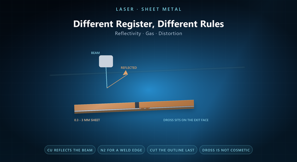
Both reflect most of the beam at the wavelength that most fibre and solid-state lasers produce, so the coupling of energy into the material is poor and variable. Copper is worse than aluminium, and a clean copper surface is worse than an oxidised one — which is why a cut that works on dirty copper can fail on the first clean sheet.
Both conduct heat extremely well, so the energy that does couple spreads sideways instead of staying at the cut. That widens the heat-affected zone and makes the cut harder to keep narrow.
Both are soft and gummy in pure form, so dross adheres rather than being ejected, and a pure copper edge is usually worse than an alloyed one.
The practical consequence is that a machine that cuts steel comfortably may need different optics, different power and a different gas to cut copper of the same thickness, and the parameter set does not transfer. A test cut on the actual alloy and temper is therefore not a formality; it is the only way to know whether the machine can do the job at all. A reflective surface also returns light into the optics, which is why copper is often cut on a machine that was specified for it rather than adapted to it.
3. Assist Gas Decides the Edge
The gas choice is the single biggest lever on edge quality, and the two options behave differently.
Oxygen adds chemical energy to the cut, so it cuts faster and thicker, at the cost of an oxidised edge and a wider heat-affected zone. On a collector the oxide matters, because the edge may be welded or coated.
Nitrogen is inert, so it cuts by melting and blowing, which gives a cleaner and brighter edge with less oxide, at the cost of speed and of higher pressure.
The choice is therefore a service question rather than a preference: a busbar edge that will be welded wants nitrogen; a rough cut that will be machined afterwards can take oxygen.
A third option, compressed air, is a compromise that is popular for aluminium and poor for copper. A collector edge that is welded and then leak-tested makes the gas choice visible twice, once at the weld and once at the test. A nitrogen edge is also easier to clean before welding, which is a step that is easy to forget in a quote.
4. Kerf and Dross on Thicker Metal
On thicker sheet the kerf is a real fraction of a millimetre and the dross is a real feature rather than a trace.
The kerf widens with thickness and with gas pressure, so the finished part is smaller than the path by half a kerf on each edge unless the cut is compensated. On a busbar with a slot, that difference is visible in the fit.
Dross is re-solidified metal on the underside, and it is the feature that decides whether a part can go straight to the next operation. On a thick copper cut it often needs mechanical removal, which is an extra step that a quote should include.
Two dross types are worth distinguishing. A hard, adherent dross points to too much energy or too slow a speed. A soft, easily removed dross points to the gas or the pressure. A dross that is only on one side of a cut is a sign of a beam that is not perpendicular, which is a machine alignment issue rather than a parameter one. A kerf that is wider than the drawing assumed also changes the fit of a slot, which is a drawing issue that shows up in assembly.
5. Heat Input and Distortion
A sheet metal collector can distort, and the distortion is a function of the cut pattern as much as of the parameters.
Three mechanisms act. A long straight cut relieves residual stress in the sheet and the part bows. A dense pattern of cuts heats the part unevenly and the part twists. And a part that is cut free early loses the stiffness the surrounding sheet was providing.
That is why a plate is usually cut with the outline last, and why a nesting that keeps the part attached until the end is more dimensionally stable than one that frees it first.
A stress-relieved or annealed sheet distorts less than a hard-rolled one, which is why the temper on the drawing is a cutting instruction as well as a material one. A part that is cut in two passes can also be cut in two states, which is a common source of a flat part that is not flat after the second pass. A distortion that appears overnight is usually residual stress rather than heat, which is why the time between cutting and measuring matters.
6. Nesting and the Sheet
A sheet metal job is priced on a sheet, so the nesting is part of the design conversation.
Three things matter. The part orientation relative to the rolling direction, because a long thin part cut across the grain behaves differently from one cut along it. The spacing between parts, because too little web transfers heat between cuts and too much wastes sheet. And the lead-in and lead-out, because a pierce on the part edge leaves a mark.
A collector plate with a large open area is also a nesting problem, because the cut is long relative to the material, and the sheet left behind is weak. A nest that keeps the parts connected to the frame until the end is also a nest that can be recovered if one cut fails. A nest also sets the sheet utilisation, which is where most of the cost difference between two quotes on the same part comes from.
7. Where Sheet Metal Habits Fail
Four habits from general sheet metal work do not transfer to a collector.
“Deburr” as a note. A sheet metal shop treats deburring as a given; on a collector edge, the direction and the method matter and a generic note hides that.
Tolerance by gauge table. A general tolerance table is written for steel; copper and aluminium move differently.
Dross as cosmetic. On a bracket, dross can be ignored; on a collector edge that will be welded or coated, it cannot.
One parameter set per thickness. Copper, aluminium and stainless at the same thickness are three different jobs.
A drawing that works for a bracket and a drawing that works for a collector look similar and are not. A shop that asks which of the four habits it is allowed to use is a shop that has cut collectors before. A habit also travels: a drawing template written for brackets carries all four of them into a collector request without anyone noticing.
8. What the Drawing Should Say
A drawing for a laser-cut sheet metal collector should state the alloy and temper, the thickness, the outline and any slots with their widths, the tolerance on the functional dimensions, the edge requirement per region — cut quality, oxide, burr, dross — and the flatness.
It should also state the process assumptions that matter: whether the edge will be welded, whether it will be coated, and whether the part will be machined afterwards.
The recurring mistakes are a general tolerance table, A drawing that states the process assumptions is a drawing that two shops will quote the same way. A drawing that names the sheet size is a drawing that can be nested as well as cut. an edge note that says only “deburr”, a slot narrower than the kerf, a flatness requirement with no measurement state, a temper left unspecified, and a quantity given without the sheet size it will be nested on.
