

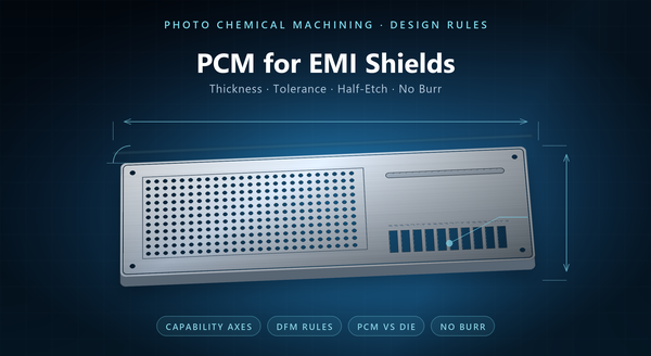
chemical machining design rules
Photo chemical machining is what engineers call the route when a part is made by chemistry rather than by a cutter: photoresist defines the shape, etchant removes the metal, and nothing touches the work. Applied to EMI shields, the point is a lid, a vent panel or a finger array produced from a file with no die, no burr and no heat. The useful question is not whether the process can make a shield, but what it holds dimension by dimension, and which rules a drawing has to respect. This page sets out those rules — thickness, feature size, tolerance, half-etch depth, forming and drawing practice — and the cases where another process is the better answer.
1. What the Name Covers
Photo chemical machining, PCM, photochemical etching and photofabrication describe the same core: a phototool carries the geometry, resist transfers it, chemistry removes what the resist does not protect. The word machining is a claim about precision rather than about contact; no chip is cut and no tool mark is left.
The term is usually reserved to distinguish it from chemical milling, which removes metal over large areas to a controlled depth, often from one face, with a mask applied by hand or through a simple stencil. PCM is the fine-feature version: both faces are imaged and etched, features are small relative to the sheet, and the depth is either a through-cut or a deliberate half-etch. Both share the chemistry. What makes shield parts repeatable is registration and process control, not the label.
2. Four Capability Axes
Capability in PCM is not one number. It is the interaction of four axes, and a drawing that fixes three of them still leaves the fourth open.
| Axis | What sets it | Practical direction |
|---|---|---|
| Sheet thickness | gauge, etch rate | thinner sheet gives finer features, tighter tolerance and a shorter etch |
| Feature size | undercut against depth | as a working rule a through-feature is comfortable at about the sheet thickness; below that it is a capability question |
| Tolerance | registration, undercut control, inspection | state a band tied to thickness, not a figure borrowed from machining |
| Edge profile | two-sided etch | the wall is slightly tapered and never vertical; it matters on mating and sealing faces |
The taper is the axis designers forget. A shield wall that seats against a housing is a wall with a profile, and the dimension that matters may be the one at the contact face rather than at mid-thickness.
Underneath the table sits one physical fact: the etchant travels sideways as it travels down. The supplier tunes the ratio between the two, which is why the same artwork on a thinner sheet comes out with a larger aperture and a squarer wall. A buyer who understands that ratio can predict which dimensions will move when thickness changes, and can ask for compensation in the right place.
3. Design Rules That Pay Off
A handful of rules cover most of the drawing problems that reach a first article.
Round the internal corners. Etchant pools in a sharp corner and the feature comes out under-etched, so a radius costs nothing in artwork and removes a recurring deviation.
Keep webs proportionate to thickness. A web thinner than the sheet distorts in handling before it ever reaches inspection, and ligaments are the first feature to suffer when a panel is rinsed.
Put alignment marks in the artwork whenever both faces carry fine features. They are the registration reference the shop actually uses, and their absence turns a small misalignment into a scrap panel.
Place retaining tabs on non-critical edges and away from sealing faces. A witness mark on a contact land cannot be inspected away, because there is nothing to compare it with.
Add a bend-relief half-etch wherever a fold is required. An unrelieved bend line wanders, and the formed angle then varies with the operator rather than with the tool.
Do not dimension a feature that sits below the capability band. Specify the field, the open area and the measured range instead, so the accept-or-reject decision rests on a number that can be met.
4. Material Behaviour
Material choice for a shield is a mechanical decision with an electrical consequence, and PCM treats the grades differently.
Spring alloys carry contact fingers and grounding springs: beryllium copper, phosphor bronze, and spring-tempered stainless where stiffness and cost matter more than conductivity. They are ordered in a temper, they must return after deflection, and they are sensitive to the heat of forming and plating.
Structural parts hold cans, lids and fences. Austenitic stainless, 304 and 316L, is the usual choice: it etches predictably, resists corrosion and keeps its shape at low thickness. Copper and brass are chosen for conductivity and solderability. Aluminium serves weight but its oxide raises contact resistance unless the part is plated. Nickel alloys appear where temperature and corrosion rule out the cheaper grades.
Two process notes follow. Etching does not change temper, so the strip arrives with the properties it was ordered with. Plating does change them, and a plated spring may need an embrittlement relief bake, which belongs on the drawing rather than in the shop’s discretion. Etch rate also differs between alloys, but the more useful question is how a grade behaves after forming: a spring that takes a set is a design fault, not a process fault.
5. Drawing Practice
A PCM drawing should describe two states: the flat pattern that is etched and the formed part that is measured. Most arguments at first article come from describing only one of them.
Dimension finished features, not artwork features. Etch compensation is the supplier’s job, and a drawing that carries pre-compensated sizes removes the supplier’s ability to hit the target.
Assign tolerance where function lives — the sealing face, the mating edge, the contact height — and leave the rest at general tolerance. A drawing where every dimension carries the same tight band is not more rigorous; it is more expensive and no more capable.
Name the datum for flatness and say how it is measured. State the finish and the sequence: etch, form, plate. Call out tabs, frame, packing, and the hand of any asymmetric feature.
The most common drawing error is a tolerance table copied from a machined part. It reads as discipline and produces a first-article argument, because the band was never achievable on a sheet of that thickness.
6. PCM Against Stamping and Laser
Each process imposes something different on the part, and the choice usually follows from volume, thickness and how settled the design is.
| PCM | Stamping | Laser | |
|---|---|---|---|
| Tooling | file only | die | file only |
| Burr | none | rolled burr, removal needed | minimal, recast possible |
| Heat and stress | none | mechanical stress | heat-affected zone, foil distortion |
| Half-etch | yes, by etch time | no | no |
| Design change | new file | new die | new program |
| Fits best | fine features, prototype to mid volume | high volume, frozen design | simple outlines, fast turnaround |
The row that decides most shield programs is the design-change row. Shields change during EMC work, and a route whose change cost is a file survives that phase in a way a die route does not. The other rows are not neutral either: a stamped lid carries a burr line the assembly has to tolerate, and a laser-cut foil carries a heat mark that may not be acceptable under a gasket.
7. Inspection and Acceptance
Inspection should measure the features the design relies on, and report them in the form the design uses.
Apertures are measured optically at several positions and reported as a range, because a two-sided etch varies across the panel and between faces. Flatness is checked on the seating face, with the method named. Contact height on a formed finger is checked on the formed part rather than inferred from the flat pattern. Plating thickness is verified where a finish is specified. Edge condition is examined for damage from handling and forming rather than for burr, which this process does not produce.
Shielding effectiveness belongs to the assembled product. A loose lid has no meaningful figure, and a supplier who offers one is measuring something else.
8. When PCM Is the Wrong Answer
PCM is not universal, and saying so is part of a useful page.
Thick sections etch slowly and consume chemistry, so a part with real wall thickness is better machined or stamped. Deep drawn shapes are outside what a flat sheet and a brake can produce. A frozen, high-volume design usually favours a progressive die. And where a conductive coating on a plastic housing meets the requirement, no metal part is needed at all.
An order should still state material and temper, thickness, flat pattern and formed state, aperture and tolerance, flatness, finger geometry, finish, tabs and packing. None of that changes the drawing rules in section five; it only changes which supplier the drawing goes to. The recurring mistakes are the ones this page has already named: a tolerance band with no thickness basis, a sharp internal corner, a dimension below the capability band, and a finish chosen before the mating metal is known.
