

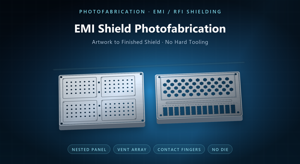
photofabrication shielding parts
EMI shield photofabrication makes shielding parts by imaging a pattern onto metal with a photoresist and dissolving the metal the resist does not protect. The artwork file is the tooling, so a shield can, lid, vent panel or finger array is produced without a die, without cutting force and without heat. That single fact shapes how these parts are designed, quoted and revised. This page follows the manufacturing route: what happens from file to finished shield, what the process can hold and where it stops, which features come with the artwork at no extra cost, and how the route behaves during the design changes that EMC work tends to produce.
1. What Photofabrication Means
Photofabrication is two operations in sequence. First the pattern is transferred to the metal by photo imaging: the sheet is coated with photoresist, exposed through a phototool carrying the part geometry, and developed so the resist remains only where metal must survive. Second, the exposed metal is dissolved by a controlled etchant. Nothing touches the part mechanically, and no heat is applied, which is why the process handles thin foil and delicate features that a die or a beam would distort.
The comparison with the alternatives is about what each one imposes. Stamping needs a die, applies force, and leaves a burr that usually needs removal; it is economical once the design is frozen and the volume justifies the tool. Laser cutting has no tooling either but introduces heat, so edges can carry a recast layer and thin sheet can distort. Photofabrication trades away both the force and the heat, and in exchange it works within a thickness range and an etch-time cost that scale with how much metal has to be removed.
2. From File to Finished Shield
The chain starts with artwork rather than with metal. Etching removes metal sideways as well as downwards, so the artwork is compensated in CAM: features are sized so that the finished part, not the image, matches the drawing. Asking whether a supplier compensates artwork is a fair question, and the answer decides whether the first article is close or needs a round of adjustment.
The sheet is then cleaned, laminated with resist on both faces, exposed and developed. Etching follows, attacking both faces at once, which is why a through-cut is roughly half as deep per side and why the two images have to be registered to each other. Resist is stripped, the parts are inspected, and only then do the secondary operations run: forming to the drawn shape, plating where a finish is specified, and final inspection.
Each stage owns a different failure mode. Cleaning decides resist adhesion. Exposure decides edge definition. Etch time and chemistry decide feature size and edge profile. Registration decides whether top-side and bottom-side features line up. Forming decides whether the finished geometry matches the formed drawing.
3. What the Process Can Hold
Capability in photofabrication is tied to sheet thickness, and the relationship runs in one direction: the thinner the sheet, the finer the feature and the tighter the tolerance. Everything follows from the fact that etchant undercuts the resist as it cuts down. A shallow half-etch moves sideways less than a full through-cut, so recessed features are held more accurately than through-cut outlines on the same sheet.
Practical limits show up as ratios rather than as absolute numbers. Minimum feature width, minimum ligament between features and achievable tolerance all scale with the thickness being etched. Edge walls are not perfectly vertical either; a two-sided etch leaves a slight profile through the thickness, which matters when a shield wall has to seat against a mating surface.
The right way to specify is therefore to state thickness first, then tolerance as a function of it, rather than carrying a tolerance number from a machined part into an etched drawing. Where a tolerance drives function, the capable value should be agreed with the supplier before artwork release, not discovered at first article. A feature list reviewed against those ratios at enquiry stage removes most first-article surprises.
4. Features That Come with the Artwork
Because the whole pattern is produced in one imaging step, features that would be separate operations elsewhere are free here. Half-etched recesses that clear a component height, stiffening ribs across a large lid, bend relief lines that make a fold predictable, pockets that locate a gasket, alignment marks, part numbers and logos all sit in the same file as the through-cuts. Mixed aperture sizes, frames and mounting holes are included in the same way.
The payoff is consolidation. A lid with recesses, formed fingers, mounting holes and its own markings can be one part rather than an assembly of several, which removes operations, fasteners and tolerance stack-up from the product.
Placement still follows rules. Retaining tabs that hold the part in its panel during processing should sit on non-critical edges and away from sealing faces, because removing a tab leaves a witness mark. Fine features belong away from tab positions, where etchant flow is disturbed. These decisions belong at artwork stage, when moving something costs nothing.
5. Formed and Spring Features
Many shields are etched flat and formed afterwards. A finger array is etched as a comb and then bent so each finger stands as a cantilever, and the contact force it delivers comes from geometry — length, width, thickness and formed angle — so the pattern is a spring design. Enough force breaks through oxide and holds under vibration; too much force wears the mating surface and can take a permanent set.
Material follows function. Spring features are usually specified in beryllium copper or phosphor bronze in a temper that returns after repeated deflection. Cans, lids and fences that only hold shape are commonly stainless steel. Copper and aluminium appear where thermal conductivity or weight leads.
The sequence matters and belongs on the drawing: etch, form, then plate. Forming after plating can crack a brittle finish; plating before forming can change the mechanical behaviour of a thin spring.
6. Panelisation and Nesting
Parts are etched as a panel, and the panel is the economic unit. Cost per part depends heavily on how many parts nest into one sheet, so the outline is a cost decision made on the drawing: an outline that tiles tightly uses material and etchant well, and one that leaves large scrap areas does not. Panel handling also sets practical limits on part size, and very large parts may be limited by the sheet and the tank rather than by the pattern.
Quantity behaves the same way. Adding parts to a run adds panels, and the setup work — artwork, resist, first-article inspection — is largely independent of how many parts follow. That is why small runs are viable and why unit cost falls with quantity in steps rather than smoothly.
Tabs, frame and nesting are one decision. A frame that helps a fragile part survive processing may cost panel area, and the right balance depends on whether the part is packed loose, on tape or in trays.
7. Revision During EMC Work
Shielding designs change late. A vent array is resized, a seam is bridged, a finger pitch is tightened after a failed scan, and each of these is an artwork change rather than a tooling change. That is the main practical advantage of the route, and it is also why revision discipline matters.
The discipline is simple but worth stating. Revisions are cheap before artwork release and progressively more expensive afterwards. Drawings should carry a revision level that matches the released file, the file should be the single reference for the pattern, and the formed state should be revised with the flat pattern rather than independently. Keeping the first article from each revision gives a reference when a later change behaves unexpectedly.
Where a design is genuinely settled and the volume justifies it, the tooling-based route becomes the cheaper one — the point at which that trade flips is a commercial decision, not a technical one.
8. When the Route Is Wrong, and Order Notes
Photofabrication is not universal. Thick material etches slowly and costs chemistry and time, so a shield that needs real section is better stamped or machined. Deep drawn shapes are outside what a flat sheet and a brake can produce. Very high volumes with a frozen design usually favour a progressive die. And where shielding can be achieved by a conductive coating or a gasket on a plastic housing, a metal part may not be needed at all.
An order should state material and temper, sheet thickness, the flat pattern and the formed state, apertures with tolerance, flatness limit, finger geometry with the contact requirement, finish, tabs and frame, quantity and packing method. The common mistakes are a tolerance carried over from a machined part with no thickness basis, a finger array with no target force or deflection, a finish chosen without naming the mating metal, and a design released as a flat pattern with no formed drawing behind it. Each is cheaper to settle before the file is released.
