

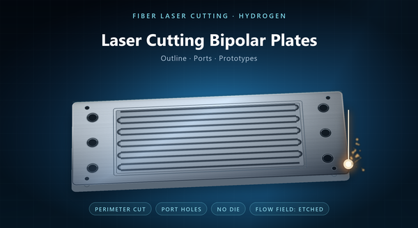
bipolar plate precision cutting
Hydrogen bipolar plate precision laser cutting is the part of plate making that happens at the perimeter: the outer profile, the manifold ports, the locating features and the coupons used to qualify a coating. Precision here means the port positions, the profile and the sealing land hold to a stated tolerance, not that the beam makes the flow field. The flow field in the middle of the plate is a different problem, and it is not what a laser is for at production volumes. Getting that division right is most of what this page is about, because a plate that is quoted as “laser cut” without saying which features can end up with a channel that cannot be coated evenly or a port edge that will not seal.
1. What the Laser Does on a Plate
A bipolar plate is a thin metal sheet with three families of features: the flow field that distributes gas or water, the ports that feed the field and pass coolant, and the perimeter that has to seal against a gasket and fit the stack fixture.
Laser cutting handles the second and third well. The profile is a contour, the ports are holes, and both come from a file with no die. On a thin plate the kerf is small and the cut is fast, so a prototype plate can be made the day the drawing is agreed.
The first family is where the process choice matters, and it is covered next.
That distinction is not pedantry. A quote that omits it gets compared against a quote that includes etching, and the two look alike on price while delivering different parts. For a stack program it also decides which supplier is credible: one who offers to cut the flow field on a laser is quoting a prototype as though it were production.
2. Why the Flow Field Is Not Laser-Cut
A flow field is a pattern of long, shallow channels with lands between them, and its quality is judged by depth consistency, land width, surface finish and edge condition, because the plate is coated afterwards and the coating has to cover the walls.
A laser cuts by melting and ejecting, so a channel cut by a beam carries a recast layer on its walls and a taper from entry to exit. Both interfere with coating adhesion, and the recast skin behaves differently from the parent metal in the corrosive environment inside a stack. Add the traverse time for hundreds of channel metres and the economics fall away.
That is why production flow fields are stamped or photo-etched, and why the etching pages in this series treat the channel as their subject. A laser can cut a channel in a prototype, and sometimes does, but it is not the process a stack program should be built on. The same reasoning explains why a laser-cut channel can look acceptable under a microscope and still fail a coating adhesion test: the geometry is there, the surface is not.
3. Cutting Thin Plate
Bipolar plates are thin, and thin sheet brings handling problems that thicker work does not have.
The plate has almost no stiffness of its own. It lifts under assist gas, it can flutter between supports, and a cut that starts accurately can wander. Supporting the sheet close to the cut, or cutting it on a carrier, is what keeps the profile true.
Nesting matters as much as it does in any sheet process, but with a twist: a plate is mostly active area, so the scrap is small and the sheet utilisation is decided almost entirely by how the perimeter shape tiles.
Stack cutting is possible and is usually a mistake on a plate this thin, because the lower layers see a different focus and gas condition and the port edges end up with different dross.
A plate that is handled carelessly between cutting and stacking picks up a bow that no later operation removes, so the packing method belongs in the flatness specification rather than in the shipping note.
4. Heat, Burr and the Sealing Land
The perimeter is a sealing land, and a sealing land has to be flat, clean and free of burr. A laser cut leaves a small dross bead on the exit side, and on a plate that is clamped against a gasket, a bead of a few hundredths of a millimetre is a leak path or a stress riser.
The heat-affected zone matters for a second reason. Where the plate is coated, the coating has to bond to the cut edge as well as the face, and an oxide layer on that edge weakens the bond. Cleaning and, where the alloy needs it, passivation after cutting are part of making a plate, not an optional step.
Ports are the other place where edge quality shows. A port edge that is ragged restricts flow and can trap debris, and a port that is out of position by more than the manifold tolerance shifts the whole stack’s alignment.
Deburring is itself a risk on a plate this thin. A mechanical deburr can round the sealing land the gasket needs flat, so the cut condition has to be good enough that heavy deburring is not the remedy.
5. Cut, Clean, Coat
The sequence is the design decision. Almost every plate is cut before it is coated, because coating first and cutting afterwards leaves an uncoated edge and a damaged film.
Cutting first means the coating has to cover a cut edge, which is a harder surface than a rolled face: it is rougher, it may carry oxide, and its geometry is a taper rather than a radius. A coating process qualified on flat coupon faces is not automatically qualified on that edge.
The practical answer is to clean and, where specified, passivate after cutting, then coat, then inspect the edge as well as the face. Where the plate is welded into a two-half assembly, the cut edge of the port is also a weld preparation, which adds another reason to keep it clean. Where coating is applied by a partner, the cut-edge requirement should travel with the drawing instead of being discovered at the coater.
6. Tolerances and Flatness
Laser cutting holds position well and holds a profile well, but a plate is judged on flatness as much as on dimensions.
Flatness is the property most easily lost. Heat from a long perimeter cut, handling of a floppy sheet and the release of rolling stress all move a thin plate out of flat, and a plate that is not flat will not seal or stack. The flatness limit and its measurement belong on the drawing, and the measurement should be taken on the face that seats.
Port position tolerance is the second number that matters, because ports are what the manifold aligns to. A profile that is generous while the ports are tight is a normal specification; the reverse is not.
A plate that meets every dimensional callout but bows by a few tenths will still fail at the stack, and the failure will usually be blamed on the gasket rather than on the plate.
7. Prototype and Volume
Laser cutting has no tooling, so it fits the phase where a plate design is still being argued about: a new port layout, a different active area, a coupon for a coating trial.
At volume the picture changes. A stamped plate needs a die, but a die produces the flow field and the perimeter in one hit, and at stack volumes that is the cheaper route. Photo etching produces the field without a die and keeps the perimeter in the same artwork, which is why etching dominates custom and mid-volume plate work.
Laser cutting therefore sits at the prototype end and at the odd-feature end: a plate trimmed after welding, a one-off coupon, a repair. It is a good tool in that role and a poor one as a volume strategy for the whole plate.
That is also why a laser-cut prototype and an etched production plate are not interchangeable for stack testing. The flow field surfaces differ, and the test result follows the surface.
8. Inspection and Order Notes
Inspection of a laser-cut plate covers the profile, the port positions, flatness on the seating face, burr and dross on the sealing land and at the ports, and the edge condition where coating will follow.
An order should state the alloy and thickness, the profile and port drawing, the critical dimensions, the flatness limit and how it is measured, the burr acceptance, the cleaning and passivation requirement, whether the plate will be coated, and the packing that keeps a thin plate from bending.
The recurring mistakes are a plate specified as “laser cut” with no statement of which features the laser makes, a flow field cut by laser because it was convenient for a prototype and then carried into production, and no flatness limit on a part whose only job is to seal. A drawing that carries the port positions, the flatness limit and the burr acceptance is short, and it is the difference between a plate that stacks and one that is argued about.
