

fine hole laser cutting EMI
EMI shield micro laser cutting covers the small features a beam makes in a shield: drilled micro holes, narrow slots and fine cut-outs, one contour at a time, instead of exposing a photoresist and letting an etchant remove the metal. It is the right tool for a narrow set of shield jobs: a few holes in a thick section, features added after forming, a curved or drawn surface that a phototool cannot wrap, or a rework on a part that is otherwise finished. It is the wrong tool for a dense vent array in thin foil, where etching is faster, cheaper and far more uniform. This page covers how the feature is made, what the process can hold, and how to specify it so the result is measurable.
1. What “Micro Hole” Means in a Shield
The word micro is relative. A hole is small in this context when its diameter is small compared with the sheet thickness, or small compared with the pitch of the array it sits in. Those are two different regimes.
In the first, the hole is deep relative to its width: a vent in a machined or cast wall, or an aperture through a folded section where two thicknesses overlap. The controlling problem is aspect ratio, and the beam has to remove material from the bottom of a blind passage.
In the second, the hole is shallow but tiny: a fine vent field in thin sheet, where a hundred small apertures sit within a square centimetre. The controlling problem is not depth but count, and the process has to place many holes quickly without letting heat accumulate.
Laser cutting is competitive in the first regime and usually loses in the second. Most of the confusion in enquiries comes from not saying which one is meant.
2. Why Laser Is Used at All
Laser brings three things that a chemical route cannot. It needs no mask, so there is no artwork, no resist lamination and no development step. It works on a surface that is not flat, which matters when the holes have to go into a drawn or curved shield wall. And it can be applied late, after the part has been formed and finished, so a missing hole or a blocked vent can be corrected without scrapping the part.
The economics follow. A single part or a handful of parts can be drilled the day the drawing arrives, and a design change is a new program. There is no bath to qualify and no chemistry to dispose of.
The trade is that the beam makes one hole at a time. That is irrelevant when there are twelve holes and decisive when there are twelve thousand. It is also why the process survives in production long after a design is frozen: a blocked vent or a late hole can be corrected on finished stock instead of being re-ordered as a new lot.
3. How the Hole Is Made
Three techniques cover most work. Percussion drilling fires a burst of pulses at a fixed point and lets the hole deepen; it is fast and produces a hole with a pronounced taper. Trepanning cuts a circular path with a smaller spot, which gives a rounder hole and better diameter control at the cost of time. Helical drilling combines the two, orbiting while it deepens, and is used where the wall quality matters more than speed.
Spot size sets the floor on diameter. A hole cannot be much smaller than the focused spot, and the effective spot grows as the beam diverges through thicker material, which is why taper increases with depth.
Assist gas does two jobs: it ejects molten material and it cools the cut. Gas choice and pressure change the amount of dross on the exit side, and the exit side is usually the harder face to keep clean.
Focus position is the setting operators adjust most. Focus at the surface gives a wider entry and a narrower exit; focus below the surface reverses part of that. The drawing should say which face is the entry, because the two faces will not measure the same.
4. What Limits the Process
Aspect ratio is the first limit. As depth grows relative to diameter, the beam diverges, the gas cannot clear the hole, and the cut turns from drilling into melting. The practical ceiling depends on the material and the gas, but the direction is universal.
Taper is the second. A drilled hole is rarely cylindrical; the entry is larger than the exit, often by a noticeable fraction of the diameter. A drawing that specifies one diameter and no taper requirement will be argued about at inspection.
Dross and spatter are the third. Ejected metal can adhere around the exit, and on a shield that sits close to a board, a spatter droplet is a short circuit waiting to happen.
Heat accumulation is the fourth, and it is specific to arrays. Drilling many holes close together raises the local temperature, and in thin sheet that shows up as distortion rather than as a bad hole. Spacing the drill order, or accepting a lower density, is often the fix.
5. Quality Signatures and What to Specify
Four things belong on a micro hole drawing: the entry diameter, the exit diameter or the taper allowance, the dross acceptance, and the positional tolerance of the hole relative to its datum.
The recast layer deserves a mention. Every laser-drilled hole carries a thin resolidified skin on its wall, and on a shield that will be plated or soldered, that skin behaves differently from the parent metal. Where the hole is a vent rather than a contact surface, it is usually acceptable; where it is a tuned aperture, it may not be.
Measurement method should be named as well. An optical measurement from one side sees the entry; a cross-section sees the profile. A supplier asked for “the diameter” will report whichever is easier, so the drawing has to remove the choice. Where the hole is small enough that the recast skin is a serious share of the wall, a cross-section is the only honest measurement, and the sample should be a sacrificial part from the same batch rather than a hand-picked one.
6. Against Etching for the Same Field
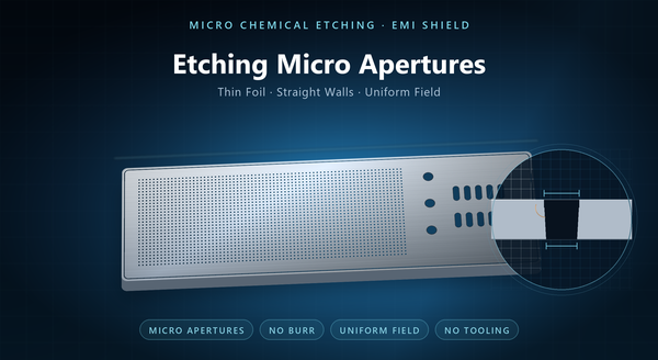
For a dense aperture field in thin sheet, etching is not merely competitive, it is the correct answer, and the comparison should say so plainly.
| Micro hole laser | Chemical etching | |
|---|---|---|
| Holes per part | tens to low hundreds | thousands |
| Hole uniformity | varies with position and order | uniform across the field |
| Taper | pronounced, entry to exit | present but small on thin sheet |
| Dross / recast | yes, needs control | none |
| Formed or curved surface | can be drilled after forming | needs a flat blank |
| Thick section | the natural case | slow and expensive |
| Adding a hole later | new program, same day | new artwork, new lot |
The row that decides most enquiries is the first. A vent field with hundreds of apertures per part is an etching job; a bracket with eight holes is a laser job. Between those, the answer depends on thickness and on how many parts are needed.
7. Design Rules for Laser-Drilled Shields
Keep a ligament between holes. Two holes that nearly touch leave a web that heats twice and can tear; the web width should scale with thickness rather than with the drawing’s convenience.
Keep holes away from edges and bend lines. A hole close to an edge weakens the rim that the beam is cutting, and a hole on a fold line becomes an oval when the part is bent.
Drill order matters in arrays. Sequencing holes to spread heat, rather than working left to right, is what keeps a thin panel flat.
State the entry face. Because the two faces differ, the face that carries the functional dimension has to be named, and the flatness that matters should be checked on that same face.
Avoid stacking. Stacked drilling is possible but the lower layers see a different focus and a worse gas flow, so the taper and dross differ from the top part. Thin panels also need to survive handling before forming, so a field that covers most of the part is easier to drill while a border still holds it flat.
8. Inspection and Order Notes
Inspection for a laser-drilled shield checks the entry and exit diameters on a sample, the taper on a cross-section, dross and recast, positional accuracy, and flatness where the part seats.
For a vent field, an airflow check is often more informative than a dimensional one, because a partly blocked hole passes a diameter check and fails the function.
An order should state material and thickness, the hole size with entry and exit definition, the pitch and ligament, the entry face, the taper allowance, the dross limit, the positional datum, the flatness limit, and whether holes may be drilled after forming.
The recurring mistakes are a single diameter with no taper allowance, a dense field specified for laser that belongs in etching, a hole placed on a bend line, and no statement of which face is the entry.
