

solder paste stencil supplier
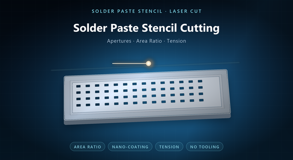
Metal laser cutting for solder paste stencil work is the cutting of one aperture per pad into a thin stainless sheet, so that a squeegee can push paste through and leave a deposit on every pad in one stroke. It is the most demanding version of stencil cutting, because the apertures are small, they are numerous, and each one has to release its paste completely on every print for the life of the stencil. This page is about the SMT case specifically: the aperture rules, the thickness strategy, the wall, and the frame.
1. The Stencil in the Printing Cycle
A print is a cycle: the stencil is aligned to the board, lowered onto it, a squeegee drives paste across the apertures, and the stencil is lifted. The paste must fill each aperture, then shear cleanly at the pad and stay there.
Two things have to be true for that to work. The aperture has to be large enough to fill and small enough to control volume, and the wall has to release. Everything else — thickness, coating, tension, frame — exists to make those two things reliable.
That is why a stencil is specified by its apertures and its wall, not by its outline. A stencil is also a wear item: apertures slowly load with dried paste, and a sheet that prints perfectly on day one can drift by week five. A clogged aperture is usually cleaned rather than replaced, which is why wall smoothness matters for the whole life.
2. Aperture Design Rules
The aperture is usually a reduced version of the pad. The reduction controls the paste volume and the release: a slightly smaller aperture prints a slightly smaller deposit, which is often what a fine-pitch pad needs.
Three shapes dominate. A rectangle is the default. A rounded rectangle keeps paste from wicking into the corners on lift. A home plate — a rectangle with one end narrowed — is used on fine-pitch pads to improve release, because the narrowing gives the paste a place to break away.
For through-hole and connector pads, apertures are sometimes split into windows or ganged, which changes the fill and the release together. Those are design decisions, not cutter preferences.
The rule that ties them together is the area ratio: the area of the aperture opening divided by the area of its wall. Below a certain ratio the paste sticks in the wall and the deposit is short. On a dense board the apertures cover a large share of the sheet, which makes the stencil itself the weak mechanical part, and handling has to respect that. Apertures that are too large print bridges between fine pads, and bridging is a rework cost that dwarfs the stencil price.
3. Thickness Strategy and Stepped Stencils
Thickness is chosen for the paste volume the board needs. A power device wants a thick deposit; a fine-pitch IC wants a thin one. On a board that carries both, a single thickness cannot serve, and the answer is a stepped stencil: the sheet is thinned locally, usually by etching or by laser ablation, so the fine-pitch area prints thin and the coarse area prints thick.
A step is a second operation, with its own registration to the apertures, and it adds cost and lead time. It is worth it when the alternative is a compromised print. The step is usually made before the apertures are cut, so the aperture datum sits on the thinned area rather than on the original face.
On a board with one dominant pitch, a single thickness with an adjusted aperture is cheaper and more robust than a step, which is why the step should be a considered decision rather than a default. A single-thickness sheet with tuned apertures remains the cheaper default for most production boards. A step is measured against the apertures, so the same datum has to serve both, and the step boundary must avoid landing across a pad.
4. The Wall, and What Finishing Does
The laser wall carries a recast skin and a taper. Both affect release.
Taper favours the print when the aperture narrows toward the board, because paste gets a clean shear line at the pad. A wall that widens toward the board holds paste at the exit.
Recast is a thin resolidified layer, rougher than the parent metal, and paste clings to it. The standard remedy is electropolishing, which removes the recast, smooths the wall and slightly rounds the entry edge. The entry edge matters as well: a sharp lip can shave paste off the squeegee and leave a smear on the next print.
Nano-coating goes further: a thin release film on the wall and the face lowers the friction between paste and steel. It is not a substitute for a good wall, but on fine-pitch apertures it is often the difference between a marginal print and a stable one. A wall that looks acceptable under a loupe can still hold paste if the recast is thick, which is why finishing is specified rather than left to the shop.
5. Frames, Mesh and Tension
A stencil can be supplied bare, or mounted.
A bare sheet is cheapest and packs flat, and it is used with a printer that has its own tensioning or clamping. It suits prototypes and low volume.
A framed stencil is bonded to a mesh and tensioned in a cast or machined frame. The mesh allows the sheet to be held at a controlled tension, which keeps it flat and improves the print.
A self-tensioning frame holds the sheet directly and can be re-tensioned in the field. It costs more and travels better. A mesh-mounted stencil has a service life too: the mesh fatigues and the bond line can fail before the steel wears out.
Tension is the number that matters: too little and the sheet sags between prints, too much and it distorts the apertures. The frame supplier’s specification should travel with the stencil. A frame that has been re-tensioned many times loses its uniformity, and no printer setting compensates for a sheet that is tight in one corner.
6. Interaction with the Printing Process
The stencil is one part of a print system, and the best stencil cannot fix a bad print.
Squeegee pressure, angle and speed decide how the aperture fills. Separation speed decides whether the paste releases or strings. Board support decides whether the stencil sits flat.
That means a stencil problem and a printer problem look alike on the deposit. Before a stencil is rejected, the print parameters should be checked, because a stencil that prints badly at one setting may print well at another. A defect that follows the aperture pattern points at the stencil; one that follows the squeegee stroke points at the printer.
A supplier who can discuss those parameters is more useful than one who only quotes a sheet. A supplier who asks about the printer is more likely to supply the right sheet than one who only asks for a drawing.
7. Prototype to Volume
A stencil follows the board revision, so every board change is a new stencil. That makes laser cutting the natural route: no tooling, a re-cut rather than a re-tool, and a turn measured in hours or days.
At volume the stencil is still laser-cut, because the volume is in boards rather than in stencils. A production line may hold several stencils per product to allow for wear and cleaning, and each is a laser-cut part.
Electroformed stencils are the alternative for the finest apertures: the wall is grown rather than cut, so it is smoother and can be thinner. They are slower to order and more expensive, and they are chosen for a specific fine-pitch problem rather than as a general upgrade. A stencil ordered for a first build is often reused for the pilot run, so the first article and the production part are the same sheet.
8. Inspection and Order Notes
Inspection covers aperture positions and sizes, wall condition, burr on the board face, flatness, and the frame or tension where one is supplied.
A print check is the functional test: print, measure the deposits, and compare against the volume the design expects. Where a fine-pitch device is on the board, that device is the one to measure. A print check on the fine-pitch device is also the fastest way to see whether the stencil is working.
An order should state the board data or the aperture drawing, the aperture reduction, the sheet thickness, the step map if any, the board face and its burr limit, the finishing (electropolish, nano-coating), the frame type and tension, and the packing.
The recurring mistakes are an aperture drawing without thickness, a step map that does not match the board, a nano-coating assumed rather than ordered, and a frame specified without its tension. A stencil that prints well on the first article but drifts by week five was probably under-specified on the coating or the wall.
