

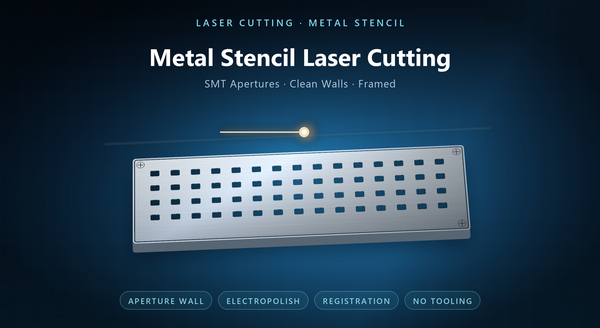
solder paste stencil laser cutting
Metal laser cutting for metal stencil work is the cutting of aperture arrays and outlines into thin metal sheet to make a stencil: the stainless sheet used to print solder paste onto a circuit board, the template used to mark or paint a repeated pattern, or the mask used in a coating or blasting step. The cut is the product. A stencil is judged by whether paste or paint passes through each opening cleanly and lands where it should, which makes the aperture wall, its taper and its surface the quality that matters, not the outline.
1. What a Metal Stencil Is
The dominant case is the SMT solder paste stencil. A thin stainless sheet carries one aperture for every pad on the board; the sheet is placed on the board, paste is squeegeed across it, and the stencil is lifted away leaving paste deposits.
The same construction serves other duties. A marking stencil has apertures in the shape of the letters or symbols to be sprayed or brushed. A coating mask has apertures for a selective finish. A blasting mask protects the areas that must not be eroded.
All of them are thin sheet plus a pattern, and all of them fail in the same way: an aperture that clogs, tears the deposit, or sits slightly off the pad. A stencil is also a consumable: it wears, it clogs, and it is replaced when the board changes, so the economics are about turnaround rather than tool life. That makes the stencil a direct expression of the board data rather than a separate engineering artefact.
2. What the Laser Cuts
The laser cuts the apertures and the outline in one program, from the same data the board or the artwork was built from. That is the practical reason laser dominates stencil making: the stencil is a direct output of the design file, and a revision is a re-cut rather than a re-tool.
For an SMT stencil the apertures are rectangles, rounded rectangles, home plates or circles, one per pad, often with a small reduction from the pad size to control paste volume. For a marking stencil the apertures are the artwork itself. For a coating mask they are windows. On a fine-pitch board the aperture may be reduced on all four sides, and that reduction is a design decision the stencil maker should not invent.
The outline is the second cut: the sheet is trimmed to the frame or to the board outline, with fiducials and tooling holes cut in the same pass so that everything registers to the same datum. The tooling holes are what the printer clamps, so their position relative to the apertures is the registration.
3. The Aperture Wall Is the Product
Paste release is governed by the wall. When the stencil lifts, paste has to shear away from the wall and stay on the pad. A rough wall, a burr at the exit, or a wall that tapers the wrong way holds paste back, and the deposit comes out short or smeared.
Three properties matter.
Taper: a laser-cut aperture is slightly wider at the entry than at the exit. For paste release, a wall that narrows toward the board is generally preferred to one that widens, because it gives the paste a clean break at the pad.
Burr and dross: the exit face can carry a small bead. On a stencil that face is against the board, so a bead holds the sheet off the board and lets paste bleed sideways. Deburring or a finishing step is standard. A stencil that releases well at one aperture size can fail at half that size on the same sheet.
Surface: a smooth wall releases better than a rough one, which is why stencils are usually electropolished after cutting. The polish removes the recast skin and rounds the entry edge slightly, both of which help release. A perfectly vertical wall is the ideal, and the practical aim is to get as close to it as the gauge and the kerf allow.
4. Thickness and the Area Ratio
Stencil thickness is chosen against the finest feature on the board, and the governing rule is the ratio of aperture area to wall area — the area ratio. A small aperture in a thick sheet has a low ratio, paste sticks in the wall, and the deposit fails.
That couples thickness to aperture size, and it is why a board with both fine-pitch and coarse parts sometimes needs a stepped stencil: thicker where the paste volume is needed, thinner where the aperture is small.
For the cutter, the practical consequence is that thickness is a material choice and the aperture is a cut choice, and the two have to be decided together. A drawing that specifies a small aperture without stating the sheet thickness has left the most important variable open. The ratio is a rule of thumb rather than a law, and a supplier should be able to name which apertures on a given board are marginal.
5. Materials and Finishing
Stainless steel — 304 and 316L — is the standard stencil material: it is strong at thin gauge, it resists the paste chemistry, and it takes an electropolish well.
The gauge is thin, and the sheet has to be flat, because a stencil that is not flat prints unevenly. Material flatness is therefore part of the specification, not just the cut. A sheet that has been rolled and stored badly will print unevenly however good the apertures are.
Finishing follows the cut. Electropolishing is the common step: it removes the recast and the burr, brightens the wall and improves release. Some stencils then receive a nano-coating or a release film, which is a supplier-specific treatment and should be named in the order rather than assumed.
Framing is the other finishing decision: a stencil can be supplied as a bare sheet, bonded to a mesh and tensioned in a frame, or mounted in a self-tensioning frame. Some houses supply the stencil pre-tensioned in a frame they own, which changes the logistics but not the cut.
6. Framing and Registration
A framed stencil is easier to handle and prints more consistently, because the frame keeps the sheet flat and registers it to the printer. A bare stencil is cheaper and packs flat, and is common for prototypes.
Registration is what makes the stencil usable. The apertures have to land on the pads, which means the stencil’s own fiducials and tooling holes must be cut from the same datum as the apertures. If the outline is cut in one operation and the apertures in another, the stack between them belongs on the drawing.
The frame also sets the usable area: the tensioned region has to cover the board plus the tooling, and a stencil designed to the board outline alone may not fit the frame. A stencil that registers to its own fiducials and not to the board’s will print off-pad on the first article and every time after.
7. Prototype to Volume
Laser cutting has no tooling, so a stencil can be cut for a single board, a first article or an engineering build. That is the normal workflow in electronics: the stencil follows the board revision. A house that can turn a board revision around in a day is worth more to a build schedule than one that is marginally cheaper.
At volume the stencil is still laser-cut, because the stencil itself is a consumable that changes with every board revision. The volume question is about the printer and the frame system, not about the stencil process.
Electroformed stencils are the alternative for the finest apertures, where a laser wall cannot be made smooth enough; they are slower to order and more expensive, and they are chosen for a specific fine-pitch problem rather than as a general upgrade. The stencil is also the part blamed first when deposits are wrong, which is why the print check matters.
8. Inspection and Order Notes
Inspection covers the aperture positions, the aperture sizes, the wall condition, the burr on the board face, flatness and the frame or tension.
A first-article print is the functional check: print the stencil, inspect the deposits, and compare against the paste volume the design expects.
An order should state the material and gauge, the aperture drawing and its reduction from pad size, the board-face and its burr limit, the finishing (electropolish, coating), the frame type and the tension, the fiducial and tooling-hole positions, and the packing that keeps a thin sheet flat. A stencil drawing that names the frame system is easier to quote than one that leaves it open.
The recurring mistakes are an aperture specified without the sheet thickness, a board face not named, a finishing step assumed rather than ordered, and a stencil drawn to the board outline without allowance for the frame. Where the board carries a fine-pitch device, the first-article print should be measured there rather than on a coarse one.
