

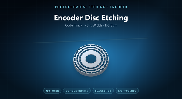
optical encoder disc etching
Metal encoder disc photochemical etching is the making of the code wheel — the thin disc with a pattern of slots and windows that a rotary encoder reads — by dissolving the pattern through a photoresist mask rather than stamping or laser cutting it. The disc is an optical part as much as a mechanical one: what it does is chop a light beam into a clean square wave, and that depends on edge quality, slit width and how true the tracks run. Etching suits that because it makes the slits without a burr, without stress, and from a file.
1. What an Encoder Disc Is
A rotary encoder couples a shaft to a disc, and reads the pattern as the disc turns. An incremental encoder uses a few tracks of evenly spaced slots and produces pulses; an absolute encoder uses several tracks coded so that each angular position is unique.
The disc is therefore a set of concentric tracks, each with its own pattern of slots at its own pitch. The tracks have to be concentric with the bore, the slots have to be the width the optics expect, and the disc has to be flat enough to stay in the optical gap. The pattern is usually the customer’s IP, so the etcher’s job is fidelity to the artwork rather than invention; the value added is edge quality and tolerance, not pattern design.
Three materials are common: glass with a chrome pattern, metal with etched or laser-cut slots, and moulded plastic. Metal is chosen where the disc must survive shock, temperature or a dirty environment, and where a thin, stiff, opaque disc is wanted. Incremental patterns are simple enough to etch at almost any pitch the optics allow; absolute patterns carry far more information per revolution.
2. Why Etching for a Metal Disc
Three properties decide whether a disc works optically: the slit edge, the slit width and the track position. Etching addresses all three.
The edge is the first. A stamping leaves a rolled burr on one face and a shear band on the other, and either scatters light at the slit. Etching removes metal chemically, so the edge is a clean line without a burr, which is what a sharp optical transition needs.
The width is the second. Etching can hold a narrow slit at a fine pitch, and the width can be tuned in the artwork rather than in a die.
The third is flatness and stress. There is no mechanical force in etching, so a thin disc arrives flat and does not carry the residual stress a stamping would put into it — which matters because a stressed disc can distort when it is mounted. Etching also leaves no tool marks to trap contamination, and no magnetic signature of the kind a stamping can impart. A chemically etched disc also has no work-hardened rim, so it can be mounted without cracking.
3. How a Code Track Is Etched
A code track is etched from both faces through a photoresist mask, and the geometry is governed by the same undercut that governs any etched feature.
A slit is a through-cut, so the etchant removes metal from both faces and meets in the middle. The mask opening sets the width at the surface, and the undercut makes the slit slightly wider than the mask at mid-thickness, or narrower depending on how the two images are registered.
That is why slit width is specified with a tolerance and measured, not assumed. At a fine track pitch, a few microns of extra width changes the duty cycle of the optical signal, and duty cycle is what the encoder’s interpolation depends on.
Track pitch and slit width are tightly coupled, and the practical limit is the ratio of slit width to disc thickness: a slit narrower than the thickness is harder to cut cleanly, and the wall becomes visibly tapered. Because the etch is two-sided, an asymmetric registration shows up as a slit that leans rather than one that narrows evenly.
4. Optical Edge Quality
The encoder does not see the disc; it sees the shadow the disc casts. That makes three things matter at the edge.
Burr is the first. A burr changes the effective slit width on one face and scatters light, and it is why a stamped disc can behave differently depending on which side faces the optics. The optics integrate across the thickness, so a slit wider at mid-thickness than at the surface still reads as a shadow of a certain width.
Edge sharpness is the second. An etched edge is defined by the resist image, so it is as sharp as the artwork; the practical limits are resist resolution and etch control rather than tool wear.
Contrast is the third. A shiny metal disc reflects as well as blocks, and stray reflection can confuse a sensor. That is why discs are often blackened — by black oxide, blackening, or a matte coating — so that the metal blocks light rather than bouncing it into the detector. A disc blackened on one face only behaves differently if it is fitted the other way round, so the treated face belongs on the drawing.
5. Geometry and Mounting
An encoder disc is a precision mechanical part as well as an optical one.
The bore is the datum. Every track is concentric to it, and the concentricity tolerance is usually the tightest callout on the drawing, because an eccentric disc modulates the pulse timing.
The hub is the second. Some discs are etched as a flat disc with a separate hub pressed or bonded in; others are etched with an integral hub or a collar. Whichever is used, the interface has to be specified, because the disc’s runout is decided there.
Flatness and balance are the third. A disc that cones will not stay in the optical gap; a disc that is unbalanced will vibrate at speed. Both are affected by how the part is handled and packed, not only by the etch. Runout is measured at the track radius rather than the rim, because that is where the optics read.
6. Materials
Stainless steel — 301 and 304 — is the common choice: it is stiff at thin gauge, it etches cleanly, and it takes a blackening treatment. 301 in a spring temper is used where the disc is large and thin.
Copper and brass appear where the disc is also a conductor or where a specific optical contrast is wanted; brass blackens well and machines predictably. Brass is heavier than aluminium at the same thickness, which changes the balance story at speed.
Aluminium is used for weight, but it is soft, and a thin aluminium disc deforms easily during handling and mounting.
Thickness is chosen against the track pitch: a finer pitch wants a thinner disc, because the slit-to-thickness ratio governs how cleanly the slit etches. A thinner disc also etches faster, which changes the cost as well as the optical behaviour.
7. Prototype to Volume
Etching has no tooling, so a new code pattern is a new artwork. For encoders, that matters because the pattern changes with resolution, with the number of tracks and with the customer’s interpolation scheme.
Prototype quantities are cut as a panel and singulated, and the same artwork runs for production. That continuity is the practical advantage: the disc that was qualified at ten pieces is the disc that ships at ten thousand. The same artwork also lets a customer try two pitches without paying for two tools.
Glass is the alternative where the resolution is beyond what a metal disc can hold; moulded plastic is the alternative at very high volume, where the pattern can be moulded in. Etching sits between them, and it is the usual answer for custom metal discs. A revision of one track is a new artwork for the whole disc, which is why the pattern file should be versioned.
8. Inspection and Order Notes
Inspection covers slit width and pitch on each track, track concentricity to the bore, disc flatness and runout, burr on both faces, and the blackening or coating.
An optical check is the functional test: mount the disc in the encoder and look at the waveform. Duty cycle and signal amplitude are the numbers that show whether the disc is good.
An order should state the material and thickness, the code pattern with track pitches and slit widths, the bore and hub interface, concentricity and flatness limits with their datums, the blackening requirement, and the packing that keeps a thin disc flat.
The recurring mistakes are a slit width without tolerance, a concentricity callout with no datum, a blackening step assumed rather than ordered, and a disc designed without considering which face the optics see. A disc that passes dimensional inspection and fails the waveform check has an edge problem rather than a size problem. A waveform with unequal marks is a duty-cycle error, and a duty-cycle error points at slit width first.
