

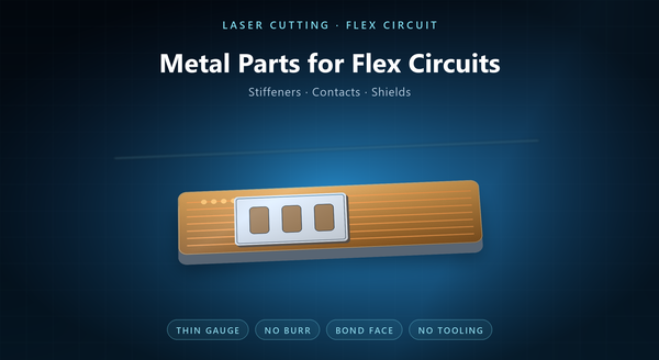
FPC stiffener laser cut, thin metal laser cutting flex
Metal laser cutting for flex circuit work is the cutting of the thin metal pieces that surround a flexible printed circuit: stiffeners that keep a connector area rigid, contacts that carry the circuit to a terminal, shields that cover a section, and carrier frames that hold the flex through assembly. The flex itself is a polymer laminate and is usually profiled by a different process. The metal parts are thin, they are bonded or soldered to the flex, and the quality that decides acceptance is the burr and the flatness rather than the outline. This page covers that work.
1. The Metal Parts Around a Flex Circuit
A flexible circuit is a sandwich of copper and polyimide, and it is flexible precisely where the design wants it to bend. That flexibility is a problem at the two ends of the circuit: a connector needs a rigid base to be soldered or crimped, and a component area needs to stay flat through reflow.
A metal stiffener solves both. It is a thin plate — stainless is common, aluminium and brass appear — bonded to the back of the flex with an adhesive or a pressure-sensitive film. It carries no current; it carries stiffness and flatness.
Contacts are the second family: small metal pieces that bridge the flex to a terminal block or a battery tab. Shields are the third, where an EMI cover is needed over a section of the flex. Carrier frames are the fourth, holding a panel of flexes through assembly and test.
Laser cutting suits all four because they are thin, flat and made in modest quantities with frequent variants. Having several of them on one panel is what makes the routing economics work: a stiffener and a carrier frame can share a sheet.
2. Materials and Gauges
Stainless steel dominates the stiffener. 301 and 304 are common, and 301 in a spring temper is chosen where the stiffener also has to resist a bend or hold a clip. The gauge is thin — comparable to the flex it supports — because a thick stiffener defeats the purpose of a flexible circuit.
Copper and its alloys appear in contacts, where conductivity matters more than stiffness. Nickel and nickel-plated steel appear where wear or solderability leads. Aluminium is used for weight and cost in shields, and it cuts quickly but deforms easily at the edge. A stiffener that is too thin will not hold a connector through insertion force.
The gauge range is the practical limit. Below a few hundredths of a millimetre the foil has no stiffness and handling dominates; above about half a millimetre the burr grows and the cut slows, and a die or an etch becomes competitive.
Material also decides the finish. A bare stainless stiffener is often left passivated; a copper contact usually needs plating, and that plating has to cover the cut edge. Temper matters as much as alloy: a hard stiffener resists bending but can crack at a tight corner, and a soft one deforms instead.
3. Why Laser, and Where It Stops
Laser cutting has no tooling, so a new stiffener outline or a new contact shape is a new program. For flex programs, which run many variants on modest volumes, that is the deciding advantage: a design change is a file rather than a die.
Laser also handles the thin gauges well because there is no clamping force to crush a delicate part, and no punch to drag the metal. A stiffener can be cut with a clean edge and a small heat-affected zone.
It stops at two places. Fine internal features — a dense array of small holes in a shield, or a slot narrower than the kerf — push toward photo etching, which leaves no burr and holds detail that a beam cannot. And high volume with a frozen design pushes toward a die, which is cheaper per part once the tool is amortised. A third route exists for the very thin cases: etching the stiffener from foil, which is how the finest flex shields are made.
Between those, laser is the right answer, and most flex programs live in that middle.
4. Thin Metal Next to a Polymer
The metal part is handled near a polyimide flex, and that changes two things.
First, heat. A laser cut leaves a small heat-affected zone and a recast skin on the metal edge. On a stiffener that is bonded afterwards, the recast is mostly a cleaning question. On a contact that is soldered, it can affect wetting, so the edge condition belongs on the drawing.
Second, particles. Cutting thin metal produces fines and dross, and a stray particle trapped between the stiffener and the flex becomes a bump under the circuit — a place where a trace can crack or a coverlay can lift. Cleaning after cutting is not optional when the part is bonded to a polymer.
The order of operations matters too. Cut, clean, then plate, then bond. A part that is plated before cleaning traps contamination under the deposit. The safest practice is to cut and clean the metal parts away from the flex assembly area, and to specify a particle limit rather than assume one.
5. Burr and Flatness for Bonding
A stiffener is bonded with an adhesive or a PSA film, and the bond has to be uniform across the face. A burr on the bond face holds the part off the adhesive, creates a void, and a void under a stiffener is a place where the flex delaminates in thermal cycling.
That makes burr a drawing callout, not a shop preference. Laser cutting leaves dross on the exit face, and which face is the bond face is a decision the designer makes. If the dross side is the bond side, a deburr step is required, and the deburr cost belongs in the quote.
Flatness is the second property. A stiffener that bows will not sit flat on the flex, and the adhesive cannot pull it down. Thin metal is not naturally flat; the rolling stress and the heat of the cut both contribute, and packing protects what is left. An adhesive cannot bridge a burr, and a pressure-sensitive film cannot pull a bowed part flat.
6. Tolerances and Registration
Three tolerances matter on a flex metal part: the outline, the position of the holes or windows relative to the flex features they must clear, and the flatness.
The outline is a normal laser profile: good position, good repeatability, with kerf compensation in the program. The registration is the harder one, because the stiffener has to align with pads, vias or a connector footprint on the flex underneath. That alignment is set by the artwork and by the tooling holes used in bonding, so the tooling holes should be cut in the same operation as the outline, from the same datum.
Flatness is specified on the bond face with a measurement method, and the packing has to protect it. A tray of loose stiffeners arrives with its edges bruised. Where the stiffener clears a via, the window is what matters, not the outer edge.
7. Prototype to Volume
Laser cutting fits the front of a flex program: a first article, a variant for a new connector, a small build for a qualification run. There is no tool to make, and the turn is measured in days.
At volume the route changes. A stiffener in a fixed shape at high quantity is cheaper stamped or photo-etched in a panel, because the cut length per part stops dominating and the tooling amortises. The sensible programme keeps laser for the variants and tooling for the runner.
The handover is worth writing down, because a laser-cut stiffener and a stamped one are not identical even when both meet the drawing: the burr direction, the edge condition and the flatness behaviour differ, and the bonding process may need to be re-qualified. A flex program that ships ten variants a year is a laser program; one that ships a single variant in thousands is a tooling program.
8. Inspection and Order Notes
Inspection covers the outline, the hole positions against the bonding datum, flatness on the bond face, burr on the specified face, and the edge condition where plating or soldering follows. For a shield, the aperture and its open area are checked as well.
An order should state the alloy and temper, the gauge, the outline and hole drawing, the bond face and its burr limit, the flatness limit and its datum, the plating and the sequence (cut, clean, plate), the packing, and the quantity.
The recurring mistakes are a burr limit omitted because the part is thin, a flatness figure with no datum, a plating callout that does not say which face is bonded, and a stiffener designed as if it were a structural plate rather than a bonded shim. A first article that records burr on both faces and a flatness trace answers most bonding questions before they are asked.
