

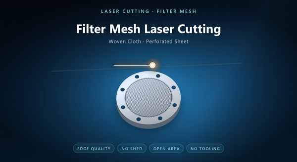
perforated grille laser cutting
Metal laser cutting for grid mesh is the cutting of a perforated field — a lattice of holes, slots or hexagons through a thin metal panel — into the grilles, vents, windows and support grids that sit in front of something that has to be seen through, breathed through or protected. The job is deceptively simple: the outline is a rectangle and the holes are circles. What makes it a real process problem is that a grid is mostly hole, and a panel that is mostly hole has almost no stiffness, no material to absorb heat, and no second chance on ligament width.
1. What Counts as Grid Mesh
The term covers several products that share one geometry: a sheet with a regular pattern of openings.
A speaker grille is the visible example, where the pattern is chosen for acoustics and appearance. A vent panel is the functional example, where the pattern sets airflow and, in electronics, shielding. An RFI window is the fine-pitch case, where the aperture has to be small relative to the wavelength of interest. A support grid holds something behind it — a filter medium, a battery electrode, a catalyst — and the pattern sets support and flow together. A battery grid is the current collector in a lead-acid or similar cell, where the pattern is the current path.
In every case the part is a panel plus a pattern, and the pattern is the product. That is why a grid drawing carries a pattern specification — pitch, hole size, stagger and ligament — rather than a list of individual hole positions, and why a change in pattern is treated as a redesign.
2. Where These Parts Go
The applications divide by what the pattern has to do.
Visibility and protection: speaker grilles, machine guards, sight windows, decorative panels. The pattern is coarse, the face is visible, and appearance matters as much as function.
Airflow and shielding: vent panels for electronics, HVAC grilles, fan guards. The pattern is chosen for open area and, where EMI applies, for aperture size against frequency.
Support and current: filter support grids, catalyst supports, battery grids. The pattern is fine, the part is often formed or coated afterwards, and the balance is between open area and mechanical integrity.
Each application stresses a different property, which is why a grid drawing should state what the pattern is for rather than only its dimensions. A grille that has to look right and a vent that has to pass air are specified by different numbers even when they come off the same machine. The aperture-against-frequency argument belongs to the RFI case, and it should be settled with the shielding engineer before the pattern is fixed.
3. Why Laser Cutting
Laser cutting has no tooling, so the pattern is a program. That matters for grids more than for most parts, because a grid program is a family: the same grille in three pitches, the same vent with a different open area, the same support grid in two thicknesses.
A die for a grid is expensive and slow to change, and a fine-pitch grid needs a fine die that wears. Photo etching produces a fine grid beautifully but needs artwork and resist for every run, and it is slow as thickness rises. Laser sits between: fast, tool-free, and happy with any pattern that fits the kerf.
It is also the only practical route for a one-off grille or a repair panel. The same programme makes it practical to cut a test panel at two pitches and choose between them on measured airflow rather than on a model. A pattern that needs no die is a pattern that can be tested in a week.
4. Cutting a Grid Is Not Cutting a Solid
A solid panel conducts heat away from the cut. A grid does not, because most of the material has already been removed or is about to be. Heat accumulates in the thin ligaments, and a ligament that gets too hot distorts, discolours or collapses.
That produces three practical rules.
Cut order matters. Working along a row of holes concentrates heat in the same band of ligaments; spreading the order across the panel lets the heat dissipate.
Piercing is the second issue. Every hole needs a pierce, and a pierce on thin material throws a small burst of spatter. On a visible face, that spatter is a defect, so the pierce point should be placed where it will not show, or the entry should be on the non-visible face.
Ligament width is the third. A ligament has to survive the heat of two adjacent cuts, so the minimum ligament is larger than the kerf and grows with thickness. In practice a grid is cut with a lead-in from the waste area rather than a direct pierce, and the waste has to be designed in so the lead-in has somewhere to start. Distortion shows first as a bow across the panel, then as a ragged ligament.
5. Edge, Burr and the Visible Face
A grille has a front. Whatever the pattern, the face that the customer sees cannot carry dross, spatter or a discoloured heat-affected zone.
Laser cutting leaves a small dross bead on the exit face. On a grille, the exit face is usually placed away from the viewer, and the entry face is the show face. That is a drawing decision: the drawing should say which face is cosmetic and which face may carry the bead.
Finishing options follow. A brushed or bead-blasted face hides small marks; anodising or powder coating covers the panel but not a burr; electropolishing removes the bead and brightens the edge.
For a functional vent or support grid, the edge matters for a different reason: a burr on a support grid can cut the medium it supports. The finish decides which process is acceptable too: an anodised grille hides a heat tint but not a raised bead.
6. Open Area, Pitch and Strength
The design variables are open area, pitch, hole shape and ligament, and they are coupled.
Open area is what the part is for: airflow, light, acoustic transmission, current. It is also what removes the stiffness. A panel at high open area behaves like a frame with a membrane, and it will bow under its own handling.
Pitch sets the visual scale and the aperture for shielding. A hexagonal pattern packs more open area at the same ligament than a square one, which is why vent panels often use hexagons and decorative grilles often use round holes.
Ligament sets strength. As a working rule, the ligament should be at least comparable to the sheet thickness, and larger where the panel is handled or clamped. A grid with ligaments thinner than the sheet is a grid that will distort in the cut and again in service. Hole shape is the visual variable: round holes read as a perforation, slots as a louvre, hexagons as a honeycomb.
7. Prototype to Volume
Laser cutting owns the front of a grid program: the first grille for a product review, a vent panel for a thermal test, a support grid for a filter trial. A new pattern is a new program, and the turn is days.
At volume the picture changes. A fixed pattern at high quantity is cheaper punched, because a die amortises and the punch is faster per hole. A very fine pattern, where the kerf is a large fraction of the pitch, is better etched.
The practical programme keeps laser for the variants and for the sizes that will never repeat, and moves the volume pattern to a die once it is frozen. The handover should be written down, because a laser grid and a punched grid are not identical: the ligament edge, the burr direction and the flatness differ. The volume pattern should also be reviewed for die feasibility, because a pitch a laser cuts happily can be too fine for a punch. The die review also catches a pattern whose webs would be too thin to survive in a die.
8. Inspection and Order Notes
Inspection covers the outline, the pitch, the hole size, the open area, the ligament width, flatness and the condition of the cosmetic face.
Open area is worth measuring rather than deriving, because a grid that meets pitch and hole size on paper can still miss open area if the pattern drifted.
An order should state the material and thickness, the pattern drawing with pitch and hole size, the open area target, the minimum ligament, the cosmetic face and its acceptance, the flatness limit and its datum, any finish, and the packing that keeps a thin grid flat.
The recurring mistakes are a pattern specified by open area alone, a cosmetic face not named, a ligament thinner than the sheet, and a volume pattern left on a laser because nobody wrote down the handover point. A pattern report giving pitch, hole size, measured open area and minimum ligament at three points is more useful than one measurement at the centre.
