

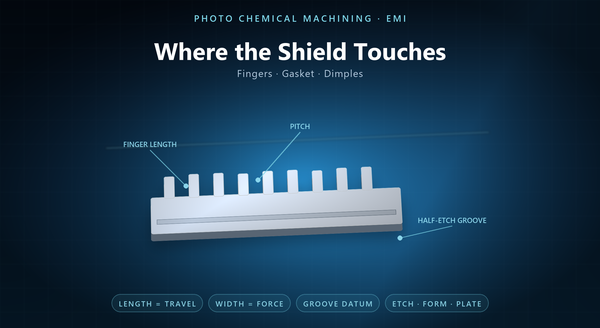
shield gasket groove etching
Photo chemical machining for EMI shield is usually discussed as a way to make apertures and outlines, and the parts that decide whether the shield actually works are neither. They are the contact features: the fingers that press on a pad or a can, the groove that holds a gasket, the dimples that locate one part against another, and the tab that a tool engages. These are compliant elements, and their behaviour is set by geometry, temper and edge quality — which is exactly what etching controls, and what stamping controls differently.
1. A Shield Works Where It Touches
An enclosure that surrounds a board but does not touch it at enough points is an antenna with a lid, not a shield.
Current has to leave the shield and return to the board reference somewhere, and the impedance of that path decides how much of the interfering energy is diverted. A few contact points with high resistance are worse than many with low resistance, and both are worse than a continuous seam — which is why a shield usually has a finger row along its whole perimeter rather than four screws.
A shield is judged by the impedance between its metal and the reference plane, and the fingers are that impedance. That reframes the part: That reframes the part: the can is the easy half, and the fingers are where the design lives. A shield bonded at one point and floating elsewhere is a shield with a stub, and the stub is the leak; a shield over a poor ground plane is a poor shield however good the fingers are.
2. The Four Numbers of a Finger
A contact finger is a cantilever spring, and four numbers describe it.
Its length sets the compliance: a longer finger deflects more at a given force, which helps with stack tolerance and hurts with resonance.
Its width sets the force at a given deflection, and the row’s total force is what the assembly feels when it is closed.
Its pitch sets how many contacts there are around the perimeter, which is a shielding number as much as a mechanical one.
Its tip shape sets how it engages: a rounded tip slides, a square tip digs, and a bent tip presents a different contact angle.
On an etched part all four come from the same artwork, which is why a finger row can be tuned without changing a tool. A row with a broken rhythm of pitches is a row with a resonance. A finger that is too short is a stiff finger, A finger that is too short is a stiff finger, and a stiff finger will not take up the tolerance of a painted seam; pitch also sets the frequency at which the row starts to behave as a continuous seam rather than as a set of points.
3. Gasket Grooves and Half-Etch
A gasket needs a groove, and a groove is a depth feature rather than a through-cut.
Half-etching produces it: the resist is left over the groove area and the etch is stopped at a controlled depth. The result is a recess with an etched floor, and its depth tolerance is a separate specification from the through-cut tolerances elsewhere on the part.
Two details matter. The groove depth should be specified from the seating face, not from the opposite side, because the gasket sees the seating face. And the groove floor should be flat enough that the gasket compresses evenly, which is a function of the etch uniformity rather than of the tool.
A groove with a rough floor compresses a gasket unevenly and leaks where it is deepest. A groove that is too deep lets the gasket bottom out A groove that is too deep lets the gasket bottom out and lose contact force; too shallow and the gasket is over-compressed and takes a set. A groove in a thin plate also thins the plate, which is a stiffness decision as well as a sealing one, and a continuous groove is itself a seam, so it has to be continuous all the way round.
4. Dimples, Tabs and Locating Features
Not every contact feature is a spring. Some exist to locate.
A dimple — a small half-etched bump or a through-hole with a raised rim — registers one part against another and keeps a finger from sliding off its pad. A locating tab does the same at a larger scale.
Etching makes these in the same operation as everything else, which removes a secondary stamping step and, more importantly, keeps them registered to the fingers they serve. A dimple that is too high lifts the finger it was meant to protect. A dimple etched as a raised ring is often enough A dimple etched as a raised ring is often enough and cheaper than a forming step, and locating features take load off the fingers, which is why they are worth designing even when the fingers alone would work.
The limit is that etching is a two-dimensional process with a depth option: it can make a dimple by leaving metal or by removing it, but it cannot form a hemispherical bump. Where a real dome is needed, a forming step follows the etch.
5. Material, Temper and Plating at the Contact
A finger is a spring, so the alloy and temper matter more here than anywhere else on the shield.
Beryllium copper and phosphor bronze are the classic contact alloys: good conductivity, good spring, predictable after forming. Stainless is used where corrosion dominates and the contact force can be higher.
Plating is the second decision. Tin is cheap and solderable but oxidises; nickel is harder and more resistive; gold is the best contact and the most expensive. A thin gold over nickel is the usual compromise on a critical finger.
Both choices change the finger: a harder temper gives more force at the same geometry, and a plating adds thickness that slightly stiffens the finger and slightly reduces the gap. A contact that is gold over nickel holds its resistance through a humid year. A plating applied before forming cracks at the bend, A plating applied before forming cracks at the bend, which is why the sequence is etch, form, plate, and a temper that is too hard is as bad as one that is too soft because it cracks.
6. Making Force and Travel Real
A drawing can specify a finger’s length and width, and it cannot specify its force directly. Force comes from geometry, temper and forming.
That means the force has to be verified rather than assumed: a deflection test on a sample, at the working deflection, with the plating on.
The forming step matters as much as the etch. A finger that is bent once has a predictable spring rate; one that is bent, straightened and re-bent has a different one, which is why the forming sequence belongs in the specification. A force specification without a deflection is a specification that cannot be tested, and the working deflection is usually stated as a percentage of the finger length — that percentage is the design decision.
Etching contributes the consistency: fingers from one sheet share a temper, so a row of them behaves as a row rather than as a set of individuals.
7. Assembly and Rework
Contact features are what an assembly feels, and they are also what rework damages.
A lid that is levered off with a screwdriver bends the fingers it passes; that is why a shield set often includes a lift tab or a half-etched fold line, so the tool has something to engage that is not a contact.
Rework also changes the plating: a finger that is bent back and forth cracks its tin, and a cracked plating on a contact is a reliability problem rather than a cosmetic one.
Both argue for designing the rework path explicitly — a tab to lift, a finger that is out of the way, a lid that can be replaced — rather than leaving it to the technician. A shield reworked twice has fingers with different histories, and a row of mixed histories is a row of mixed forces; a replaceable lid is cheaper than a reworked can, and both are cheaper than a field failure.
8. Specifying and Inspecting Contact Features
A drawing for a contact feature should carry the finger length, width and pitch, the tip shape, the working deflection and the force at that deflection, the gasket groove depth with its datum, the dimple height or depth, the alloy and temper, and the plating.
Inspection covers the geometry, the groove depth, and — for a critical row — the force at the working deflection.
The recurring mistakes are a finger specified with no working deflection, a groove depth measured from the wrong face, a plating allowance forgotten so the finger arrives too stiff, and a rework path that was never designed.
The drawing should name the sample size for a force check. An order should also say which of these are checked, An order should also say which of these are checked, and on how many pieces, because a force check on one finger out of forty is not a check on the row. A groove depth check is a cross-section or an optical depth measurement, and it should be made on the part rather than on a coupon.
