

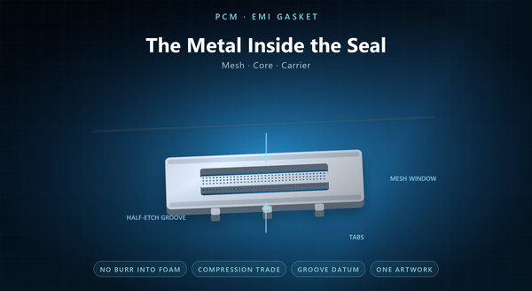
EMI gasket metal core
Photochemical machining for EMI shielding gasket is about the metal inside the seal. A shielding gasket has to do two jobs at once — close a gap against dust and moisture, and conduct across that gap — and the two jobs pull against each other: more compression is better for sealing and worse for the elastomer’s life, and more metal is better for conduction and worse for compliance. The etched part sits in the middle of that trade, and its geometry, its edge and its plating are what decide which side of the trade the gasket lands on.
1. Two Jobs, Two Failure Modes
A gasket fails as a seal or it fails as a conductor, and the two failures look different in the field.
A seal failure is ingress: dust, moisture or a cleaning fluid gets past the gasket and the assembly corrodes or shorts. A conduction failure is intermittent contact: the shield works on the bench and fails in the chamber, usually because the compression relaxed or an oxide layer grew.
Both failures are usually attributed to the elastomer, and both are often the metal’s fault. A metal core that is too stiff keeps the elastomer from conforming; A gasket is the one part of a shield that is designed to be compressed, which is why its metal is never a flat plate. A metal core that is too stiff keeps the elastomer from conforming; a metal mesh with a burr punctures the foam; a plating that is galvanically wrong corrodes at the joint. A gasket that conducts but does not seal lets moisture in, and moisture is what turns a contact into a corrosion cell; one that seals but does not conduct is a seal with a hole where the gasket is.
2. Four Constructions
Most shielding gaskets are one of four things.
A finger strip is a formed metal strip with cut fingers, and it is the only construction that is pure metal. A finger strip is also the easiest to rework and the least tolerant of misalignment. Its compliance comes from the fingers, and its conduction is direct metal-to-metal.
A mesh-over-foam gasket is a knitted or woven metal mesh wrapped around an elastomer core. The mesh conducts, the foam provides compliance, and the failure mode is the mesh abrading through the foam.
A knitted mesh tube is the same idea without the foam, compressed between two flanges.
A formed metal gasket is a stamped or etched sheet with a bead or a dimple pattern, used where the flange itself provides the load. A mesh-over-foam gasket is the most common construction in consumer equipment and the one where the metal’s edge matters most; a knitted tube is used where the flange is narrow and the compression high, and a formed metal gasket where the flange is the spring and the gasket is only the conductor.
Etching appears in the mesh, in the core of a formed gasket and in carrier frames; rarely in a finger strip, which is usually stamped.
3. Where Etching Fits
Three places, and each has a reason.
An etched mesh is a perforated sheet rather than a knitted cloth. It is stiffer, it holds a shape, and its aperture is exact — which matters when the gasket is also a vent or when the shielding requirement is band-specific.
An etched core is a formed sheet with a bead or dimple pattern, half-etched where the bead needs to be thinner. The advantage over stamping is that the bead pattern can be revised without a die.
A carrier frame is a flat frame that holds an elastomer gasket in place and provides the conductive path to the housing. An etched mesh can also carry a solid border in the same piece, which is how a gasket gets a locating edge without a second part, and a carrier frame is often the largest etched part in an assembly and the one with the tightest outline. It is a natural etched part: flat, thin, with tabs that clip and a footprint that has to match the housing exactly.
4. The Compression Trade
Every gasket has a compression-deflection curve, and the metal part moves it.
More metal in the section makes the gasket stiffer: it takes more force to reach a given compression, and the contact resistance at that compression is lower. Less metal makes it softer: easier to compress, but the contact resistance depends more on the plating and the surface.
The design question is therefore not “how much metal” but “at what compression does the gasket both seal and conduct, and what force does that need”. A softer gasket that still conducts is usually the better answer, and the harder one to design. The flange, the screw pitch and the elastomer all enter that calculation, and the metal part is one of the inputs. The curve is usually measured rather than calculated, because the elastomer dominates it, and a gasket specified at a compression the flange cannot reach is a gasket that will never conduct.
An etched mesh has an advantage here: its open area can be tuned independently of its thickness, so the stiffness and the conductivity can be adjusted on separate axes.
5. The Edge Is the Elastomer’s Problem
A burr on a metal mesh is not a cosmetic defect; it is a blade.
In a mesh-over-foam gasket the mesh is in contact with the foam under compression, and a burr on the inner face will cut into the foam over time, especially under vibration. The gasket then loses compression, and the conduction fails before the seal does.
Etching leaves no burr, which is one of the few places where a process choice directly extends a product’s life. A stamped mesh needs a deburr step, and a deburr step is a cost and a variation.
The same argument applies to a formed metal gasket that sits against a soft plating: a burr scrapes the plating off the mating surface and creates a corrosion cell. A burr on the outer face is less dangerous because it faces the housing, and deburring a fine mesh distorts it, which is a second cost of the same burr.
6. Grooves, Tabs and Frames
The carrier frame is where the etched design earns its keep.
A frame usually carries a groove for the elastomer, tabs that locate it in the housing, and a footprint that has to clear the screws and the connector cut-outs. All of those come from one artwork, which is what keeps the groove concentric with the housing.
A half-etched groove is a common feature: it locates the elastomer without adding a separate part, and its depth is the compression allowance.
The frame also has to be stiff enough not to bow between screws, which is a thickness decision as much as a design one. A frame that is half-etched for the groove is thinner there, so the groove depth is limited by the frame’s stiffness, and a frame with too few tabs will bow — a bowed frame is a gasket with a gap in the middle.
7. Plating and the Galvanic Joint
A gasket joins two surfaces, and if the three metals are galvanically mismatched, the joint corrodes.
Tin over copper is a common finish for a metal gasket; nickel is used where wear matters; silver is used where the contact resistance has to be very low, and it is expensive and tarnishes.
The plating choice is constrained by the housing: a tin-plated gasket against an aluminium housing is a milder couple than a silver one, though both will corrode in the presence of moisture.
Etching contributes here by keeping the surface clean: a part that comes out of the process without oil or oxide takes a plating that adheres, and an adhering plating is a corrosion barrier rather than a coating. A silver gasket against aluminium is a corrosion experiment with a good conductor, and a tin finish is the easiest to rework because it can be reflowed.
8. Specifying and Testing
A gasket drawing should state the construction, the alloy and thickness, the mesh aperture and open area where relevant, the groove depth and its datum, the compression range, the plating, and the flatness of the mating face.
Testing splits into three: A seal test at the working compression is the only test that proves both jobs at once. Testing splits into three: a compression-deflection test on the gasket, a contact resistance test at the working compression, and a seal test at the same compression. Transfer impedance and shielding effectiveness are tested on the assembly, and the drawing should say so rather than imply a number.
The recurring mistakes are a mesh specified without its open area, A compression-deflection test is cheap and catches the most common failure before the assembly is built, and a contact resistance test at the working compression is worth more than one at full compression. The recurring mistakes are a mesh specified without its open area, a groove depth with no datum, a plating chosen without reference to the housing, and a compression range that the flange cannot deliver.
