

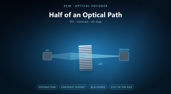
encoder slit diffraction
Photochemical machining for optical encoder disc is usually discussed as a patterning problem, and it is one — but the pattern only matters because something is looking at it. Move to the optical side of the gap and the same disc looks different: a slit is no longer a dimension but a diffracting aperture, blackening is no longer a finish but a contrast budget, and flatness is no longer a tolerance but a clearance that has to survive thermal growth and a splash of oil. This page takes that view: what the light path demands of the disc, and what etching can and cannot give it.
1. The Disc Is Half of an Optical System
An optical encoder is a light source, a disc, a mask or a second track, and a detector. The signal is the product of all four, and a disc that is perfect in isolation can still produce a poor signal if the rest of the path is wrong.
That matters for a disc supplier in a specific way: some complaints that arrive as “the disc is bad” are really the gap, the LED ageing, or a dirty window. A supplier who understands the optical side can tell those apart, and a supplier who does not will re-etch a disc that was never the problem.
The useful framing is that the disc contributes three things: an edge, a contrast, and a flatness. Everything else in the signal belongs to the head. A disc datasheet that quotes only aperture is therefore incomplete, because half of the signal is not on it. The head’s own tolerance is usually the larger term, and it is the one a disc supplier cannot fix.
2. Diffraction at Small Slits
A slit that is small compared with the wavelength stops behaving like a shadow.
At 20 µm and a near-infrared LED the effect is modest; at 5 µm it is dominant, and the light that passes a slit spreads rather than forming a sharp rectangle. The detector then sees a blurred edge, and the interpolator sees a softer zero crossing.
The practical consequence is that slit width and wavelength are chosen together. A disc designed for a 850 nm head is not automatically right for a 630 nm head, even at the same pitch, because the diffraction pattern scales with the ratio of slit width to wavelength.
That is also why a very fine disc is often used with a shorter wavelength and a smaller detector: the optics has to cooperate with the pattern, not compensate for it. It is also why a smaller slit does not always give a better signal. A disc sold as 20 µm with no wavelength has an assumption hidden inside the number.
3. Contrast and the Detector’s Range
Contrast is what the detector sees: the ratio of light through a slot to light through a land.
A bare stainless land reflects as well as it blocks, so part of the “blocked” signal is stray light bouncing into the detector. Blackening raises the contrast by absorbing rather than reflecting, and it is the cheapest optical improvement available to a disc.
The detector has a finite dynamic range, and it also has a threshold. A disc with low contrast forces a lower threshold, which makes the signal more sensitive to dust, to LED ageing and to the gap. A disc with high contrast gives the comparator room.
Contrast is therefore a specification, not a cosmetic choice: a blackened disc and a bare disc at the same slit width are not the same component. The cheapest way to widen the contrast budget is to blacken the land, not to widen the slot, and contrast degrades with contamination before it degrades with wear.
4. The Gap, Flatness and Contamination
The disc runs in an air gap, and the gap is where the optical and mechanical requirements meet.
A disc that is not flat does not run at a constant gap; it modulates the gap once per revolution, which modulates amplitude once per revolution, which shows up as an error at the rotation frequency and its harmonics. That is a mechanical defect that looks like an optical one.
Contamination in the gap does the same thing intermittently: a particle that sits between the disc and the window scatters light and produces a spike. At fine pitches a single particle can cover a track.
The disc’s contribution is to be flat and to be clean, A particle sitting in the gap covers a whole track at a fine pitch and almost nothing at a coarse one. The disc’s contribution is to be flat and to be clean, and a drawing that specifies flatness but not packing is only half a specification. Thermal growth moves the gap as much as any mechanical error, and a gap that is too small amplifies dirt while one that is too large amplifies diffraction.
5. What Duty Cycle Means Optically
Duty cycle is usually presented as a geometry number, but it is an optical one.
The detector integrates the light over its own aperture, which is wider than a slot. If the slot and land are equal in geometry but the illumination is not uniform across the aperture, the integrated signal is not 50/50. The disc can be perfect and the duty cycle still off, because the head is not uniform.
On the disc side, the duty cycle is set by the etched width and by the edge profile. An hourglass wall passes a slightly different amount of light than a parallel wall, which is one more reason the waist matters.
The useful test is therefore a waveform, not a micrometer: the disc is judged by what the detector produces. The fixed mask in the head has the same duty-cycle problem, and it is usually the mask that gets adjusted, not the disc.
6. Transmissive and Reflective Are Different Parts
A transmissive disc is judged on opacity and edge; a reflective disc is judged on the reflectivity of the marks and the diffuseness of the background.
For a transmissive disc the failure is leakage: a land that is thin enough to transmit, or a pinhole in the coating, produces an offset. For a reflective disc the failure is specularity: a surface that is bright at one angle and dark at another produces a signal that depends on alignment.
Etching produces the transmissive case naturally, because a through-slot is opaque by construction. That is the one optical requirement etching satisfies for free. The reflective case usually needs a second process — a plated or polished band, or a controlled etch texture — and that is a specification the drawing has to carry. A plated band is a process step, and it belongs on the drawing as such; a reflective disc in a transmissive head is not a degraded part, it is the wrong part.
7. Where Etching Reaches Its Optical Limit
Etching is not the only way to make a disc, and the optical requirement is what sets the boundary.
Glass with a chrome pattern holds a sharper edge and a finer feature than an etched metal disc, and it is the choice when the pitch is very fine or when the edge has to be a hard transition.
Moulded plastic is the choice at high volume with a coarse pattern, where the optical requirement is modest.
An etched metal disc sits between them: robust, thin, blackenable, and capable of an edge that is sharp enough for most encoders. Its limit is the combination of feature size and thickness, not the material.
A programme that starts on etched metal and later needs glass has not failed; it has moved to a different optical requirement. A metal disc can also carry the fixed mask itself, which removes an alignment from the head, and the pattern can be split between disc and mask to halve the feature size on each.
8. Specifying the Optical Side
An optical specification for a disc should carry four things beyond the pattern.
The first is the contrast requirement, stated as a minimum ratio at the detector, with the finish that achieves it.
The second is the slit width with the wavelength it is intended for, because the two are coupled.
The third is the flatness and the gap it has to hold, with the mounting face named.
The fourth is the acceptance test: An optical specification with no finish named is an unfinished specification. The fourth is the acceptance test: a waveform at a stated head, or a contrast measurement at a stated illumination. The optical numbers should be agreed before the pattern is frozen, because they can change the finish and the grade.
An order should also state the alloy and thickness, the pattern with track radii and pitches, the measurement face, the bore and its datum role, the blackening or reflective treatment, and the packing.
The recurring mistakes are a contrast requirement with no finish named, a slit width quoted without a wavelength, a flatness callout with no mounting face, and an acceptance criterion that names a micrometer where it should name a waveform.
