

stainless steel shim design rules
Stainless steel shim photo chemical machining is decided at the drawing stage, not at the tank, because the geometry on the sheet settles whether the chemistry can produce it at all. A stamped or laser-cut part can be redrawn almost freely: a sharp internal corner, a web the width of a hair, two holes nearly touching. Etching is a different contract. It removes metal from both faces at once, it attacks sideways as well as downwards, and it leaves the part sitting in the sheet until something cuts it free. Those three facts generate every rule below — aperture against gauge, web width, hole pitch, inner corner radius, tie bars, large open areas. Each rule is a sentence a designer can apply before the file is released, and each carries a prohibition that costs far more to fix after etching than to avoid.
1. Why Etching Does Not Inherit Stamping Rules
Start with the mechanics, because everything that follows is a consequence of them. Etching is isotropic: the etchant works downwards at roughly the same rate it works sideways, so every cut edge carries a taper that grows with depth and with time in the bath. Stamping severs metal with a tool and laser vaporises it; both finish a cut in one pass, which is why a stamping drawing can call a zero corner radius and a hairline web without argument. An etched shim cannot make that claim.
There is also no force. Nothing presses the sheet, so nothing needs a die — but nothing holds a free island in place either. And the part is never cut free feature by feature: it stays attached to the panel by whatever metal the drawing left standing.
Design for photo chemical machining is therefore not a restatement of sheet-metal rules. It is the discipline of leaving enough metal in the right places, and of keeping every feature inside a taper the chemistry can actually hold.
2. Aperture Diameter Against Gauge
A hole is the feature most often drawn smaller than the thickness behind it can support. The etchant enters from both faces and meets in the middle. In thin stock it breaks through cleanly and quickly; in thick stock it has to travel further sideways, so the wall closes in and the aperture arrives with an hourglass section. Entry and exit diameters differ, and a drawing that names one diameter says nothing about the other — which is how a comfortable-looking callout becomes an argument at inspection.
The design rule is to keep the aperture at or above the gauge. A hole the same size as the sheet is routine; the same hole in stock several times thicker is a negotiation, and the answer depends on the taper the supplier will accept rather than on the nominal diameter.
The prohibition follows: never dimension a hole by diameter alone on a drawing that matters. Give the diameter, the gauge, the face at which the diameter is measured, and whether the exit may be smaller than the entry.
3. Web Width: The Metal That Has to Survive
Where a hole is metal removed, a web is metal that has to survive, and it is the constraint designers underestimate most often, because a web reads as leftover space rather than as a specification.
Three rules cover most cases. Keep the narrowest web at or above the gauge, since the web must carry the part through etching, stripping, rinsing and packing, and a web thinner than the sheet is the first thing to distort. Keep webs in a chain equal in width, because the narrowest one sets the limit for the whole chain and the surplus is wasted metal. Watch the intersections as well: two webs meeting at an acute angle leave a point that etches from three directions at once and thins faster than either web, so a Y-junction should be drawn as a generous radius rather than a star.
Edge margins follow the same logic. Metal between an aperture and the outline behaves like a web, so an outline that hugs a hole is a thin web in disguise, and a feather edge will not survive stripping.
4. Hole Pitch and Local Open Area
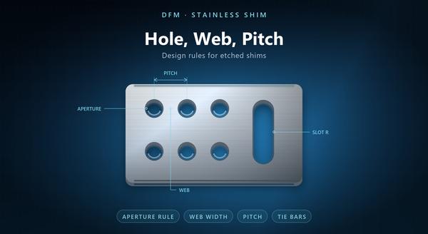
Pitch is aperture plus web, and it governs how the etchant behaves locally rather than how the part looks. A dense cluster is a region where the chemistry is depleted faster than it is refreshed, so the cluster etches more slowly than the open field beside it, and the same nominal aperture comes out smaller inside the array than outside it. That is the mechanism behind the familiar complaint that a hole pattern is generous at the edges and tight in the middle.
Stagger the rows instead of aligning them, keep a solid border of metal around an array, and balance open area across the panel. Two parts of very different density on one sheet etch differently, which is a panel-layout decision rather than a part decision, and it is worth flagging before the tool is made.
The prohibition is local density shock: do not place a nearly open field next to a nearly solid one and expect a single etch time to serve both. Say which regions are critical before photo chemical machining starts, and the panel can be laid out around them.
5. Inner Corner Radius
A sharp internal corner is the most expensive line on a shim drawing, because the etchant will cut a radius there whether or not one was drawn. The corner sees etchant from two directions, the resist has least support at the vertex, and the result is a radius set by undercut — uncontrolled, variable with gauge, and impossible to inspect against a zero callout. Drawing R0 does not buy a sharp corner; it buys a dimension nobody can hold.
Specify the radius you want instead. A workable floor is half the adjacent web, or the gauge, whichever is larger, and a corner where two cuts meet should be opened into a teardrop rather than left as a knife edge.
External corners are the opposite case: the taper rounds them anyway, so a sharp outer corner describes something the process quietly improves. The one place to be strict is a corner that will see bending fatigue, where the radius is a design requirement rather than an etch artifact.
6. Tie Bars and Part Retention
Every part has to stay attached to the sheet until someone decides to remove it. That sounds like a handling detail and is really a drawing rule: an island of metal with no tie bar falls into the etchant, and a part held by one thin tab rotates, bends, and arrives out of flat.
Give each part at least two ties, placed on a non-functional edge, wide enough to survive the whole wet process — the gauge is a reasonable starting width. Put them where a witness mark will not matter, because a broken tie leaves a small raised pip or a nick on the edge it was cut from, and on a sealing land that pip is a leak path.
Nested parts can share a tie bar, and sharing is usually the cheaper layout, but shared ties must be strong enough for the whole group rather than for one part. The deeper question of tab number, position and break-out belongs on the retaining tabs page; here the rule is simply that no feature may be an orphan.
7. Large Openings and Half-Etched Fields
A large opening is easy to etch and hard to keep flat around. The cutout itself takes the same time as any other feature; the trouble is the frame left around it, which behaves like a thin beam. A narrow frame around a big window bows during rinse and dry, and a shim that was flat on the etcher can arrive dished.
Two rules help. Keep the frame width around a large opening at or above the gauge, and if handling matters more than weight, break a very large cutout with one or two ribs rather than leaving a picture frame.
Half-etched fields carry their own constraints. A recess should not exceed half the gauge, or the remaining metal is too thin to control; a half-etched island needs a full-thickness border around it; and a half-etch running up to a through-cut needs the two faces registered to each other, a tighter demand than either feature alone. Keep a half-etched legend off any sealing land, and state in the drawing which side the recess is on.
8. Drawing Conventions and What to Confirm
A drawing that can be quoted without a phone call carries six things: a 1:1 DXF or flat-pattern STEP, dimensions taken from datums rather than from etched edges, the tolerance with the face at which it is measured, the edges that are functional as distinct from cosmetic, the flatness limit with its packing implication, and a note on which surfaces seal.
Two conventions save the most time. Do not dimension to a feature the taper will move, and do not scale a drawing to fit a sheet — the etcher images at final size, so a scaled file is a dimensional error before it is a design.
Ask the supplier to confirm four things against your drawing: the aperture-to-gauge ratio they will hold, the narrowest web for the gauge, the taper they allow at a through-cut, and whether a tie-bar witness mark is acceptable on your part. Those four answers decide whether a drawing is ready for photo chemical machining, and they are worth having before the tool is made.
