
Chemical Etching Process – Complete Industrial Step-by-Step Workflow
1. Overview of Chemical Etching Process
The core principle: protect the non-processing area with acid-resistant photoresist mask, expose the required outline and microstructure to etching solution, and dissolve metal into soluble ions through redox reaction at room temperature.
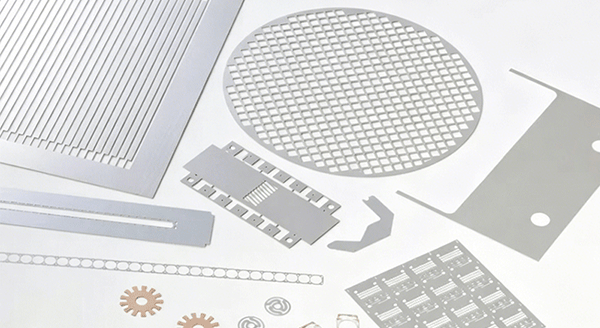
Entirely different from stamping (mechanical shear stress), laser cutting (thermal ablation and heat-affected zone), wire EDM and CNC milling, the chemical etching process features stress-free, burr-free, no material hardening, controllable half-depth etching and tool-free customization. It is widely applied on stainless steel, copper alloy, aluminum, titanium, nickel alloy thin plates ranging from 0.01mm ultra-thin foil to 2mm thickness for electronics, medical, aerospace and new energy precision components.
2. Standard 7-Step Industrial Chemical Etching Process
Step 1: Raw Material Inspection & Surface Pre-Treatment
- Incoming inspection: Check metal sheet flatness, thickness tolerance, surface scratch, oxidation and material grade consistency; warped plates need leveling first.
- Degreasing: Ultrasonic alkaline cleaning removes oil, fingerprint, cutting fluid and organic contaminants on the surface. Grease will cause poor photoresist adhesion and local missing etching.
- Micro etching / Pickling: Weak acid solution removes natural passive oxide film on stainless steel, aluminum and titanium, creating a slightly roughened micro surface.
- Drying: Hot air fully dry the workpiece to prevent water spots affecting photoresist coating uniformity.
Step 2: Photoresist Lamination / Coating
- Dry film photoresist: Hot roller laminating machine presses photosensitive dry film tightly onto both sides of the metal sheet, suitable for thick plates and high precision parts.
- Liquid photoresist: Spin coating or roller coating evenly covers liquid UV resist, mostly used for ultra-thin foils below 0.05mm.
The coated film must be uniform, no bubbles, no wrinkles, consistent thickness across the whole panel.
Step 3: UV Exposure & Pattern Transfer
- Import CAD design file to output high-precision film negative (phototool) with the required part outline, holes, grids, half-etched lines.
- Align the negative precisely on the photoresist-covered metal plate, fix by vacuum to avoid shifting.
- Ultraviolet light irradiation: The area covered by the transparent graphic on the negative is exposed, photoresist occurs polymerization reaction and becomes insoluble to developer; the black masked area remains unexposed and soluble.
For double-sided symmetrical parts, double-side alignment exposure is adopted to ensure upper and lower graphic coincidence.
Step 4: Developing & Mask Curing
- Developing process: Spray alkaline developer onto the plate to wash away unexposed soft photoresist. The designed metal area is fully exposed, while the rest is covered by hardened resist protection.
- Visual inspection: Check for broken lines, incomplete development, residual resist residue, tiny blockages on micro holes. Defective panels return for rework.
- Post-bake curing: Low-temperature oven heating strengthens the chemical resistance and adhesion of the remaining photoresist mask, preventing it from being corroded or swollen by hot etching liquid during long spraying etching. This step directly reduces undercut over-etching risk.
Step 5: Core Etching Reaction (The Key Chemical Etching Process)
- Etchant preparation:
- Stainless steel, copper, brass: Ferric chloride main solution with additives (stabilizer, wetting agent, defoamer)
- Aluminum alloy: Phosphoric-nitric acid mixed acid or weak alkaline etchant
- Titanium alloy: HF+HNO3 mixed special acid (strict safety control required)
- Controlled etching parameters:
- Liquid constant temperature (usually 45–55℃ for ferric chloride)
- Double-sided balanced spray pressure
- Concentration and Baume degree of etching solution
- Conveying speed to control etching time
- Isotropic chemical dissolution:
The exposed metal is dissolved ion by ion by etching liquid. Machine speed decides whether to etch through the plate (full cut-out parts) or stop halfway (half etching for bending grooves, positioning steps).
Engineers pre-set lateral undercut compensation according to plate thickness to offset side erosion, so finished dimensions match CAD drawing tolerance.
Step 6: Resist Stripping & Multi-Stage Rinsing
- Stripping: After reaching target depth, use strong alkaline stripping liquid to completely peel off all remaining photoresist protective film.
- Cascading pure water rinsing: Multiple tank overflow washing removes residual etching chemical on surface and tiny metal particles to prevent delayed corrosion and spot rust.
Step 7: Post-Treatment, Inspection & Packaging
Common post-treatment options
- Passivation: Rebuild compact anti-rust passive film on stainless steel, aluminum alloy to improve salt spray resistance.
- Surface treatment: Blackening, matte finishing, light brushing, sandblasting as customer requirement.
- Deburr & sorting: Although etching edge is naturally burr-free, ultra-small fragments are blown off by air gun.
Final QC inspection
- Dimensional measurement by 2D optical imager for length, hole diameter, half-etched depth tolerance
- Appearance check for pitting, uneven etching, pinholes, scratches
- Flatness test for thin foil warpage
3. Key Controllable Parameters in Chemical Etching Process
- Etching liquid temperature: Higher temperature speeds up etching rate but increases side undercut; low temperature leads to slow efficiency and uneven reaction.
- Spray pressure: Too high pressure causes mask impact peeling; too low pressure leads to liquid accumulation and blind holes not fully etched.
- Baume degree of ferric chloride: Higher concentration faster cutting speed, higher undercut value; lower concentration better edge sharpness.
- Conveying line speed: Determines total reaction time and final etching depth (through cut / half etch).
- Photoresist thickness: Thicker resist improves protection but reduces graphic resolution; thin resist for ultra-fine gaps.
4. Inherent Advantages of This Process Flow
- Entire room-temperature cold processing, zero thermal stress and mechanical stress, metal material properties fully retained.
- Edges naturally smooth without burrs, no secondary deburring needed.
- One-step half-etch integrated forming impossible for stamping and laser cutting.
- No hard mold cost, only phototool film needed, fast prototype delivery within 1–2 days.
- High consistency for mass production, no tool wear causing batch quality drift.
- Complex irregular shapes, dense micro holes, encoder gratings, ultra-narrow slits can be mass-produced stably.
5. Limitations of Chemical Etching Process
- Mainly suitable for flat thin sheet metal, poor effect on thick block and deep 3D parts (electrochemical etching is alternative for curved surface marking).
- Isotropic etching inevitably produces slight undercut, ultra-high aspect ratio microstructures are restricted.
- Special metals like titanium require hazardous mixed acid, demanding strict waste liquid treatment and safety operation management.
6. Typical Application Industries Based on This Process
- Electronics & Semiconductor: EMI shielding covers, lead frames, spring contacts, heat sink grids
- Medical Devices: 316L stainless steel filter mesh, surgical instrument parts, titanium alloy implant components
- Aerospace: Thin shims, lightweight ventilation panels, sensor pressure diaphragms
- New Energy: Battery collector mesh, fuel cell flow field plates, new energy vehicle sensor shrapnels
- Precision Instruments: Encoder grating discs, optical slits, aperture diaphragms
- Industrial Filtration: Chemical and water treatment stainless steel filter elements
Conclusion
By adjusting etching solution formula, temperature, pressure and line speed, manufacturers can realize stable precision manufacturing for nearly all conductive thin metal sheets. As high-end manufacturing continuously raises requirements for part miniaturization and high reliability, the mature chemical etching process will keep being optimized toward higher resolution, lower undercut and greener recyclable etching fluid systems, serving precision component production across multiple advanced industries.