

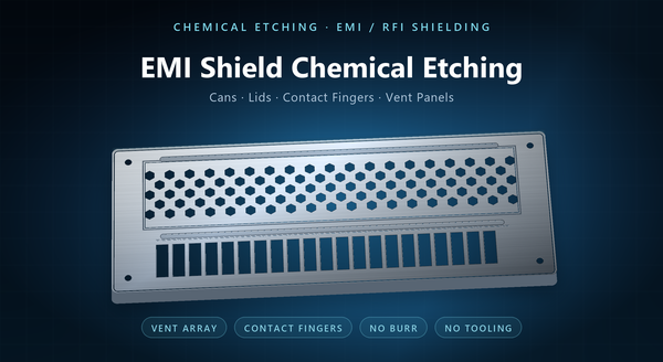
chemical etching EMI shielding
Custom EMI shield chemical etching turns a flat metal sheet into a shield can, lid, vent panel or set of contact fingers without a die. Custom means the pattern is the customer’s: aperture layout, outline, finger pitch and tabs are drawn to fit the enclosure, and a variant costs a new file rather than a new tool. Chemical etching and photochemical etching name the same route: resist defines the shape, etchant removes the metal, nothing touches the part. That matters because a shield is rarely a simple box: it has to enclose a circuit, let heat and air move where they must, make reliable contact to a ground plane, and do all of this within the few millimetres of height a modern assembly allows. This guide covers what a shield has to do, why the process fits, how material, aperture pattern and contact design interact, and the specification details that decide whether a shield works in the assembly.
1. What an EMI Shield Has to Do
A shield provides a continuous conductive path around the volume it protects. Energy arriving at the enclosure is reflected or absorbed, and the current that flows has to reach ground without crossing a gap. Three things break that path: apertures, seams and poor grounding. An aperture is any opening, deliberate or not — a vent array, a display window, a connector cut-out or the gap between a lid and its fence. A seam is the joint between two conductors, such as a lid on a can, and it behaves as a slot if it is long and unbridged. Poor grounding leaves the shield floating, so the current has nowhere to go and the enclosure couples energy instead of blocking it.
The consequence for design is that shielding is a property of the assembly, not of a part. A lid with excellent material and a poor contact pattern performs worse than a plainer part that is properly grounded and clamped. Shield design is therefore the disciplined reduction of every aperture and seam to a size the assembly can tolerate, plus a grounding path that is short and wide.
2. Why Photochemical Etching Fits Shield Work
Etching removes metal chemically through a photoresist mask, so there is no cutting force and no heat. Three consequences matter for shields. First, edges arrive burr-free and free of mechanical stress, and a lid that sits on a fence needs a flat, undistorted edge to make contact along its whole length. Second, the process handles thin foil without the distortion a blanking die or a laser can introduce, and most shield cans and lids are made from thin material. Third, the pattern is data, so changing the vent array, the finger pitch or the outline costs a new file rather than new tooling — which is what happens repeatedly during EMC compliance work.
Etching also produces features that other routes charge extra for. Half-etched recesses, stiffening ribs, alignment marks and bend lines go into the same sheet at the same time as the through-cuts. A lid with recessed areas, a formed finger array and its own mounting holes can be one part rather than an assembly of three.
3. Material and Finish Selection
Material choice splits by what the part has to do mechanically. Spring contacts and cantilever fingers are usually specified in beryllium copper or phosphor bronze, because they deflect repeatedly and must return. Shield cans, lids and fences that only hold shape are commonly stainless steel, which gives stiffness and corrosion resistance at low thickness. Copper and aluminium appear where thermal conductivity or weight leads. The enquiry should state the function — spring, structure, thermal path or barrier — rather than only a grade, because the same outline in the wrong temper will either take a permanent set or fail to hold a contact force.
Finish is part of the electrical design, not decoration. A plating layer sets surface conductivity, galvanic compatibility with the mating surface and oxidation behaviour over the product life. Tin, nickel, silver and gold over nickel are all used, and the choice depends on the mating metal, the environment and the frequency range. Plating is applied after forming, so the sequence belongs on the drawing: etch, form, plate, inspect.
4. Apertures, Vent Arrays and Open Area
Ventilation and shielding pull in opposite directions, and the etched pattern is where the compromise is written. The general rule is that an array of many small apertures shields far better than one large opening of the same total area, because leakage scales with the longest dimension of an opening rather than with its area. A designer who needs airflow buys it with hole count and pitch, not with hole size. Round holes, slots and hexagonal cells all etch readily, and a hexagonal array packs more open area into the same panel than a square one.
Open area and thickness interact as they do in any etched part. Higher open area means more metal removed and a longer etch. Thinner sheet gives more open area for the same pattern but less stiffness, and a panel that bows will not seal against its frame. Ribs, a surrounding frame or a second layer restore stiffness at some cost in open area. Aperture dimension, minimum open area and thickness should therefore reach the supplier as three linked requirements, with a note on which one may move.
5. Contact Fingers, Seams and Gaskets
The seam is usually the weakest part of a shield, and contact fingers are how an etched part closes it. A finger array is etched flat as a comb along an edge, then formed so each finger stands as a cantilever. Contact force comes from the geometry — length, width, thickness and formed angle — so the pattern is a spring design. Enough force is needed to break through oxide and hold under vibration; too much force wears the mating surface, makes assembly hard and can take a permanent set.
Finger pitch sets how often the seam is bridged, and pitch is chosen against the frequency range of concern. Where an all-metal finger is not suitable, a formed gasket, a conductive elastomer or a wire-in-elastomer strip can be specified instead, and the etched part then provides the groove or land it sits in. Whatever the approach, the grounding path has to be stated: which surface mates, where the current leaves the shield and how many contact points carry it.
6. Forming, Half-Etched Features and Assembly Details
Most etched shields are etched flat and formed afterwards, so the drawing carries both a flat pattern and a formed state. Simple bends, drawn walls and finger arrays are formed on a brake or in a fixture; where geometry repeats at volume, a dedicated form tool can be justified and amortised differently from a die.
Half-etching adds depth without cutting through. Recesses that clear a component height, stiffening ribs across a large lid, bend relief lines that make a fold predictable, and pockets that locate a gasket or a label are all routine. Because they sit in the same artwork as the through-cuts, they add no tooling cost and no part to the bill of materials.
Assembly features belong in the same review. Mounting holes, locating slots, pick-up areas for automated placement, and retaining tabs holding the part in its frame should be placed before artwork release, because a change afterwards is no longer free.
7. Cost Drivers from Prototype to Volume
An etched shield has no hard tooling, so its cost is built from artwork, material, etch time, forming, finish and inspection. That structure is why prototypes, engineering builds and low-volume production fit the process: a design change costs a file, and the same file runs for one part or a few thousand.
The drivers that move unit price are sheet thickness, open area, tolerance, part size and quantity. Thicker material etches more slowly and needs more chemistry and time. Higher open area removes more metal. Tighter tolerances and tighter flatness add inspection and may add process steps. Large parts are economical only when they nest well on the panel, so the outline and the panel layout are one decision.
Stamping becomes cheaper per part once volume justifies a progressive die and the design is frozen. The useful comparison is not which process is cheaper in the abstract, but which is cheaper given a design that is still changing, a quantity not yet fixed, and a tolerance a die may struggle to hold.
8. Inspection and Order Notes
Inspection of an etched shield covers the features that decide fit and contact. Outline dimensions and aperture size are measured optically. Flatness is checked on a surface plate or by profile, because a lid that bows will not make contact along the fence. Finger height and formed angle are checked against the formed drawing, plating thickness is verified where a finish is specified, and edge condition is examined for burrs or damage from handling and forming.
Shielding effectiveness is measured on the assembled product, not on a loose part, so compliance evidence belongs at assembly level. An order should state material and thickness, the flat pattern, the formed state, apertures with tolerance, flatness limit, finger geometry and contact requirement, finish, tabs and frame, and packing. The common mistakes are a vent pattern specified by open area alone, a finger array with no target force or deflection, a finish chosen without the mating metal, and no defined ground path. Each is cheaper to settle before artwork release.
