

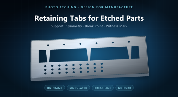
photo-etched parts retaining tabs
Retaining tabs look like a minor detail on an etched drawing, but they decide whether a part survives the process at all. In photo chemical etching the part outline is etched through the sheet, and anything fully cut free would drop into the etchant. Tabs are the unetched bridges that hold the part to its frame until someone deliberately breaks it out. Their number, position and width sit where process stability, edge quality and assembly cost meet, which is why they belong on the drawing rather than in a supplier default.
1. Why Etched Parts Need Retaining Tabs
Every through-cut part needs a temporary connection to the sheet. Etching removes metal from both faces at once, so the moment the outline is complete, the part is free. Rinsing, drying, inspection and packing all involve movement, and a loose part can be lost, bent or scratched against its neighbours. Tabs keep the part registered in the panel through every one of those steps.
The requirement is temporary because the tab has no function in the finished assembly. It exists to be removed, which means it should be designed for removal from the start. A tab strong enough to survive the etch line but leaving a torn edge at assembly has traded one problem for another.
Tabs also carry information. Their position tells the operator how the part sits in the frame, and a tab left on a non-critical edge can double as a handling feature during coating, plating or assembly. For very small or thin parts, the tab may be the only practical way to keep the part from being lost before it reaches the customer.
2. How Tabs Interact with the Etch Process
A tab is not neutral to the chemistry. It masks the area directly beneath it, so the metal behind a tab etches less than the rest of the part, an effect often called tab shadow. On thin sheet the shadow is small, but on thicker material it can leave a visible step or a slightly under-etched edge. Designers who ignore it sometimes find a feature near the tab comes out undersized.
Tabs also disturb etchant flow. Fresh chemistry reaches the part more slowly in the lee of a tab, and the local undercut can differ from the rest of the outline. This matters most next to fine features, where a small change in undercut is a large fraction of the feature width. Keeping tabs away from the finest detail is cheaper than trying to compensate for the disturbance.
The tab itself is etched from both sides while the rest of the part is being cut. Its cross-section thins as the etch progresses, so the finished tab is always narrower than the artwork. A tab that looks generous on the drawing may arrive as a thin neck, and that is a common reason parts break loose in the tank. The artwork should therefore specify the tab as a finished dimension, not as a pre-etch width.
3. Designing Tab Number, Position and Width
Number comes first. A single tab lets the part rotate like a pendulum, so the minimum is usually two, and larger or heavier parts need three or four. The right number is the smallest that keeps the part flat and registered through the line, because every extra tab adds a witness mark and a break-off step.
Position follows mass and geometry. Tabs work best when they are symmetric, close to the centre of mass and spread around the outline, so the part cannot sag or twist. They should stay away from sealing faces, datum edges and fine features, because those are the surfaces that cannot tolerate a witness mark or a local flow disturbance. A tab on a scrap area or a non-critical edge is almost free; a tab on a sealing land can cause a leak path that no inspection will catch.
Width scales with part weight and sheet thickness. As a starting point, a tab should be wide enough to survive rinsing and handling but narrow enough to break without tearing. Thicker sheet needs a wider tab for the same part weight, and long, unsupported parts need either more tabs or a stiffer frame. Tab length matters too: a short tab is stiffer than a long one and transfers less bending to the part.
Shape is a design variable as well. A straight tab is simple to etch and easy to snap. A tab with a notch or a narrowed neck creates a controlled break point and a smaller witness mark, at the cost of one more feature on the artwork. A dog-bone shape can keep the tab stiff while narrowing only at the break line.
4. Break-Off Methods and Witness Marks
Break-off is a design decision as much as a process step. A tab can be snapped by hand, cut with a fixture, nibbled with pliers or trimmed with a blade, and each method leaves a different edge. Hand snapping is fastest but least controlled; a fixture gives repeatability at the cost of tooling; cutting removes the tab cleanly but adds labour.
Notching the tab at the part side is the usual way to control the break. The notch concentrates stress, so the tab fails at a predictable line instead of tearing across the parent metal. The remaining nib is the witness mark, and its acceptable height should be stated on the drawing. A witness mark that is acceptable on a hidden bracket is not acceptable on a visible face or a sealing surface.
Where the tab lands matters as much as how it breaks. A tab on a non-critical edge can be left as a small nib; a tab on a machined or coated surface may need a secondary clean-up step. For parts that will be coated, the break should happen before coating if the witness mark would disrupt the film, or after coating if the coating would embrittle the tab.
5. Frames, Packing and Handling
Parts can ship on the frame or broken out and packed. Shipping on the frame protects flatness and edges, keeps small parts from being lost and makes incoming inspection faster, at the cost of extra material and shipping volume. Breaking out at the supplier reduces volume but shifts the risk of damage to the packing.
The choice usually follows part size and customer assembly. Large, thin or high-value parts travel better on the frame. Small parts that feed an automated line may need to arrive loose and oriented, which means the tab design has to support clean separation and the packing has to prevent tangling.
Frames also carry handling features. A frame can include holes for hanging, stacking or robot pick-up, and those features cost nothing extra because they are etched in the same step. Designing the frame together with the tabs avoids a second operation later.
6. Inspection and Acceptance
Inspection should check the tab as a finished feature, not just the part outline. Tab width, position, witness mark height and flatness after break-off are the four measurements that predict whether the part will assemble cleanly. A first article should record all four, and the sample should be broken exactly the way production will break it.
Acceptance criteria should distinguish cosmetic and functional edges. A nib on a hidden edge may pass with a generous limit, while the same nib on a sealing face may fail. Writing the limit per edge, rather than one number for the whole part, prevents arguments at incoming inspection and gives the supplier a clear target.
Tab break surfaces also work as a free process indicator. A sudden change in witness mark height usually means etch time or resist thickness has drifted, and the break surface shows it before dimensional inspection does.
7. Specifying Tabs on the Drawing
The drawing should show tab locations, the finished tab width, the break method, the acceptable witness mark and whether the part ships on frame. Leaving tabs to a supplier default is acceptable only when the part has no critical edges and no tight flatness requirement; otherwise the default will be chosen for the supplier’s process, not for the assembly.
A short note on the drawing is usually enough. State the tab width as a finished dimension, mark the break line, and name the edge that must stay clean. If the part will be coated, add whether the break happens before or after coating. These few lines remove most of the ambiguity that otherwise gets resolved by a phone call after the first article.
8. Common Failure Modes
Most tab problems are predictable. Too few tabs produce a part that twists or sags. Too narrow a tab breaks in the tank and the part is lost. A tab on a sealing face creates a leak path. A tab without a notch tears the parent metal and leaves a burr that no deburring step will reach. A tab placed next to a fine feature disturbs the local etch and the feature comes out undersized.
Each failure has a design fix, and each fix is cheaper before the artwork is made. That is the practical argument for treating tabs as part of the drawing: they are small, but they sit at the point where process, quality and assembly all meet.
