

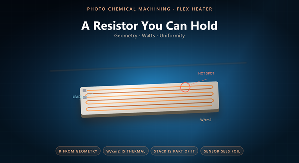
flexible heater watt density
Photo chemical machining for flex circuit covers a family of parts, and one of them behaves quite differently from the rest: the etched foil heater. A signal flex circuit is judged on its impedance and its continuity; a heater is judged on how many watts it delivers, how evenly, and to what. A heater is also the one flex part whose failure can be smelled. That shift — from an electrical part to a thermal one — That shift — from an electrical part to a thermal one — changes the design rules, A heater is also a part that is judged by feel before it is judged by a meter, because the customer touches it. That shift from an electrical part to a thermal one changes the design rules, and it is where most flex heaters are won or lost. A heater also fails differently: an open circuit is easy to find, and a hot spot is not, because the part still works while it degrades.
1. A Heater Is a Flex Circuit Without a Signal
An etched foil heater is a laminated flex circuit whose conductor is a resistor.
The construction is familiar: a metal foil, an adhesive, a polyimide film, a coverlay. What is different is that the conductor is not there to carry a signal from A to B; it is there to dissipate power along its whole length.
That single change means the trace is no longer a wire but a heating element, and every property of the trace — width, thickness, alloy, length — becomes a thermal design variable rather than an electrical one.
2. Resistance Comes From Geometry
The resistance of an etched trace is set by its geometry and its alloy: resistivity times length, divided by width times thickness.
Etching contributes two of those four numbers directly — the width and the length — and it contributes them with a precision that matters, because a small width error is a proportional resistance error, and a resistance error is a power error at a fixed voltage.
A foil that is work-hardened etches differently from an annealed one at the same nominal thickness. It also contributes the uniformity. It also contributes the uniformity. A foil that is too thin is easier to etch and harder to make uniform, because a small thickness variation is a large resistance variation. It also contributes the uniformity. A heater with a resistance tolerance of a few percent is a heater with a power tolerance of a few percent, which is why the width tolerance is the first number to negotiate. A photochemically etched trace holds its width along a long serpentine path, which is what makes the power density even along that path.
3. Power Density and Hot Spots
The number a heater is specified by is usually watt density — watts per unit area — and it is a thermal limit rather than an electrical one.
A hot spot is a place where the local watt density exceeds what the surrounding stack can carry away. It arises from three causes: a narrower trace, a tighter spacing between traces, or a region where the thermal path is worse than the rest of the part.
A hot spot that is invisible on a thermal image is not a hot spot. That is why two heaters with the same total resistance That is why two heaters with the same total resistance A heater that is asked for a high watt density and a fast response is a heater that is being asked to break the stack. That is why two heaters with the same total resistance can behave very differently: one distributes its watts evenly and the other concentrates them at a corner. A hot spot also has a time dimension: a modest excess that lasts a second is harmless and the same excess that lasts an hour is a delamination.
4. Uniformity
Uniformity is a design outcome, and it has three inputs.
The trace width tolerance sets how much the resistance varies along the path. The trace spacing sets how much the neighbouring traces heat each other. And the edge of the heater sets a boundary condition: the outermost trace has a neighbour on one side only, so it runs cooler or hotter than the middle depending on the stack.
Designers handle the edge in three ways: A trace that runs along the very edge of a trimmed part can lose width in the trim, which is a yield issue rather than a design one. Designers handle the edge in three ways: by running a wider trace at the perimeter, by accepting an edge band outside the specified area, or by adding a thermal spreader. A serpentine also has a turn radius, and a turn is a place where the current crowds and the local watt density rises.
5. The Stack Is Part of the Heater
An etched foil heater is never used bare. It is laminated, adhered or clamped to something, and that something is what actually gets heated.
Three layers matter. The insulation between the foil and the target sets the thermal resistance and the safe touch temperature. The adhesive sets the thermal contact, and a void in the adhesive is a hot spot. And the target itself has a thermal mass, which sets how fast the heater can respond.
A stack that is compressed in a housing is a stack whose insulation thickness is a function of the screw torque. A heater specified only by its resistance A heater specified only by its resistance is a heater specified without its stack, A stack that is clamped rather than bonded has a contact resistance that varies with the clamp force. A heater specified only by its resistance is a heater specified without its stack, and the two together are what the application sees. A stack with a large thermal mass is slow but stable, and a stack with a small one is fast and jittery, and the control loop has to match the one it has.
6. Sensing and Control
Many flex heaters carry their own sensor, and the sensor is usually an etched resistance element on the same foil or on a second layer.
Three consequences follow. The sensor measures the foil, not the target, unless it is placed on the target side. The sensor’s own resistance is small and its leads are thin, so it is sensitive to the lead resistance. And the sensor and the heater are thermally coupled through the stack, which gives a fast response and a steady-state offset.
A heater with a sensor on the same layer is a compact part A sensor that is etched as a long thin trace is also a sensor that is fragile. A heater with a sensor on the same layer is a compact part and a part whose control loop has to be tuned for that offset. A four-wire measurement removes the lead error and adds two more connections, which is a trade worth making on a precision heater and not on a simple one.
7. Termination
The termination is where a flex heater most often fails, and it is a mechanical problem rather than an electrical one.
Three forms are common: a soldered lead, a crimped terminal, and a connector tail. Each has a thermal issue, because the termination sits at the edge of a hot part and expands with it.
A termination that is rigid at a hot edge is a termination that will crack. That is why the tail is usually relieved, A crimp that is made cold is a crimp with a resistance that grows. That is why the tail is usually relieved, and why the lead material should match the foil’s expansion rather than the housing’s. A termination that is potted is protected from moisture and trapped against the heat, which is a trade rather than a solution.
8. What the Drawing Should Say
A drawing for an etched foil heater should state the alloy and foil thickness, the trace width and its tolerance, the path length, the resistance at a stated temperature, the watt density at a stated voltage, the heated area, the stack (insulation, adhesive, target), the sensor if any with its placement, the termination, and the dielectric withstand.
It should also state the safe touch temperature and the environment, because both constrain the watt density more than the electronics do.
A heater that is specified by area alone is a heater that will be delivered with the wrong resistance. The recurring mistakes are a heater specified by resistance alone, A heater that is specified by watts alone is a heater that will be delivered with the wrong area. A drawing that names the stack and the environment is a drawing that can be checked against a thermal model rather than against a hope. The recurring mistakes are a heater specified by resistance alone, a watt density quoted without a stack, a sensor assumed to measure the target, a termination designed without a strain relief, and a uniformity claim made without naming the area it applies to.
