

bipolar plate cross leak,
Photochemical machining for hydrogen bipolar plate is usually discussed as a flow-field problem, and the flow field is the easy half to describe. The hard half is that the plate carries three fluids at once — hydrogen, air and coolant — and the value of the plate is decided less by how well each channel flows than by how completely the three stay apart. This page is about that separation: the ports, the manifold, the gasket groove, and the leak paths that a drawing can prevent.
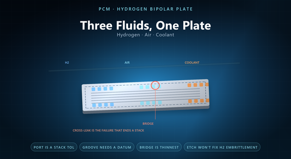
1. Three Fluids, One Plate
A bipolar plate is three devices laminated into one thickness.
On one face, hydrogen flows through a field of channels. On the other, air flows through a second field. Between them, coolant flows through a third circuit, or through the same plate’s internal passages.
Each of the three has its own inlet, its own outlet, its own manifold run and its own sealing requirement. And all three are separated by a few tenths of a millimetre of metal and a gasket groove.
A plate is also the only part in the stack that touches all three fluids at once. That is the design problem: That is the design problem: the plate is thin, the three circuits are close, and the only thing between hydrogen and air is a groove and a gasket. A plate that leaks internally still works on a test bench, which is why the separation has to be proven rather than assumed.
2. Ports and the Manifold
The ports are where the stack feeds the plate, and they are the most constrained features on it.
A stack of a hundred plates has a hundred ports that must line up. That means the port position tolerance is a stack-up tolerance, not a part tolerance: what matters is that every plate in the stack shares the same port centre, so the manifold is a straight tube rather than a staircase.
That is why port positions are usually etched in the same operation as the flow field, from the same artwork, rather than drilled in a second process. A drilled port and an etched field are two different registrations.
The manifold is also where a stack’s tolerances accumulate fastest, because every plate adds a port and a gasket. The manifold also decides the flow distribution. The manifold also decides the flow distribution. A port that is off centre by a tenth of a millimetre in one plate is a port that is off centre by ten millimetres after a hundred plates. A plate near the stack inlet sees a different pressure than one near the outlet, and the port area is what the designer uses to bias the distribution.
3. The Gasket Groove
The gasket groove is the feature that makes the three circuits separate, and it is a depth feature rather than a through-cut.
Three things about it matter. Its depth sets how much the gasket is compressed, which sets both the sealing force and the gasket’s life. Its floor has to be flat enough that the gasket compresses evenly. And its width has to match the gasket’s own tolerance, because a groove that is too wide lets the gasket move.
That is why the groove depth has to be specified with a datum, and why the datum should be the face the gasket sits against rather than the opposite face.
A groove that is too deep is a groove that lets the gasket bottom out and lose its preload. A groove is also a place where the etch behaves differently: A groove is also a place where the etch behaves differently: A groove that is narrower at the bottom than at the top is a groove that grips the gasket, which is sometimes wanted and usually not. it is a large half-etched area, so the local etch rate and the local undercut are not the same as in the fine flow field.
4. Cross-Leak Is the Failure That Matters
A bipolar plate can fail in several ways, and the one that ends a stack is a cross-leak.
Three paths are possible. Hydrogen into air, which is a safety event rather than a performance one. Coolant into gas, which floods an electrode. And gas into coolant, which pressurises the coolant loop and shows up as a mysterious level rise.
Each of the three has a different cause. Hydrogen into air is usually a gasket failure at the port or the manifold edge. Coolant into gas is usually a groove that is too shallow or a gasket that has taken a set. Gas into coolant is often a crack at a manifold bridge, which is a thin metal web between two ports.
A bridge that is wide enough to be safe is sometimes wider than the port pitch allows, which is when the port layout has to change. That last one is worth designing for explicitly: That last one is worth designing for explicitly: A cross-leak is also the failure that is hardest to diagnose in the field, because the symptoms appear on the other side of the system. the bridge between two ports is the thinnest structural feature on the plate, and it is loaded by every pressure difference the stack sees.
5. The Coolant Circuit
The coolant circuit has its own requirements, and they are different from the gas fields.
A coolant circuit that is shared between two plates has one more interface to seal than a separate one. Flow distribution matters more than pressure drop, Flow distribution matters more than pressure drop, A coolant field that is designed for pressure drop is a coolant field that starves its far end. because a plate that starves a region runs hot there and the membrane dries or degrades. That is why coolant fields often use a different channel pattern from the gas fields, with more parallel paths and a shorter route.
Coolant chemistry matters too. Fuel-cell coolant is usually deionised water with a corrosion inhibitor, and its conductivity is monitored — so a plate that releases ions raises the conductivity and trips an alarm. That is a material and surface issue rather than a flow one, and it is why the coolant-side surface is often specified with a passivation or a coating.
6. Hydrogen Embrittlement, Stated Honestly
Hydrogen embrittlement is a real material concern for high-strength steels, and it is worth being precise about what it means for an etched plate.
It is a bulk material behaviour: it depends on the alloy, its strength level and the hydrogen it absorbs. Etching does not change the alloy’s susceptibility, and it does not make a plate more resistant.
A crack that starts at an etched edge starts at a stress raiser that could have been a radius. What etching does affect is the surface state and the edges, What etching does affect is the surface state and the edges, A plate that is etched and then ground at the seal face has a worked surface where the gasket sits, and that is a different surface. which are where a crack would start. A burr-free etched edge and a properly passivated surface reduce the number of initiation sites, and that is a real contribution — but it is a contribution to crack initiation, not to the alloy’s resistance.
A plate specification should therefore choose the alloy for the environment and use the etch for the edge, rather than expecting the etch to solve a metallurgical problem.
7. Alignment and Assembly
A stack is assembled by hand or by a machine, and the plate has to make that possible.
Three features help. A locating tab or a dowel hole registers the plate to its neighbour. An asymmetric port pattern makes it impossible to install a plate the wrong way round. And a visible orientation mark lets an inspector confirm the stack without disassembling it.
A stack assembled with one plate reversed is a stack that has to be taken apart. All three are etched features, All three are etched features, and all three cost nothing at the artwork stage and a great deal if added later. An asymmetric port pattern is the cheapest poka-yoke in the whole stack.
8. What the Drawing Should Say
A drawing for a hydrogen bipolar plate should state the three fluid circuits separately, each with its port positions, its field geometry and its own sealing requirement.
It should state the gasket groove depth with its datum, the port position tolerance in stack terms, the manifold bridge width, the alignment features, the surface treatment for each face — because the coolant face and the gas faces see different chemistry — and the leak test that proves the separation.
A drawing that names the leak test also names which separation is being proven. The recurring mistakes are a plate specified as a flow field and not as three circuits, A drawing that separates the three circuits is a drawing that a stack engineer can check against the manifold. a port tolerance written as a part tolerance, a groove depth without a datum, a manifold bridge that nobody checked, and a coolant face specified with the same treatment as the gas face.
