

metal bipolar plate machining
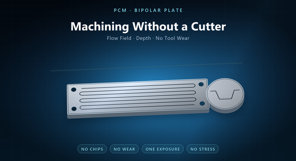
Photochemical machining for metal bipolar plate is worth discussing as machining rather than as etching, because that is the decision a plate programme actually faces: the flow field has to be produced to a depth, a width and a flatness, and the question is which process can produce it repeatably at the volume in question. PCM removes metal chemically through a photoresist mask, so it machines without a cutter, without chips and without tool wear — and those three absences are the argument.
1. Machining Without a Cutter
A machining process is judged by three things: what shape it can leave, how closely it holds it, and what it costs per part. PCM answers the first two from a phototool, and the third from the number of parts on a panel.
There is no cutter, so there is no tool radius to design around, no cutter deflection at the end of a long channel, and no tool wear that drifts the depth from the first plate to the thousandth. The absence of a cutter also removes the fixture, the programme and the coolant that a machined plate would need.
The metal is removed by chemistry rather than by shear, so the plate is not work-hardened at the flow field and carries no residual stress from the cut. For a plate that will be coated and then stacked under compression, both are worth having. A phototool is also inexpensive next to a die, which is why the route is used before a design is frozen.
2. What It Changes Against Milling
Milling a flow field is a mature route, and it remains the right one for a thick plate or a deep channel. PCM changes the picture in four specific ways.
The first is speed with density. A milled field costs time per channel; an etched field costs one exposure for the whole pattern. The more channels and ports on the plate, the larger the advantage. The chemistry is not selective between features either, so a deep port and a shallow channel on the same plate are set by masking rather than by a tool change.
The second is the end of the channel. A miller leaves a radius set by the tool; an etched field can end in any shape the artwork draws, which is how a turn or a distribution feature is made without a second operation. A drawn turn is also smoother than a milled one, because there is no direction change for a cutter to negotiate.
The third is thinness. A milled plate has to be thick enough for the cutter to work in; an etched plate can be thin, which matters for stack height and for weight. Thinness is what makes a high-power-density stack possible at all.
The fourth is stress. Milling induces stress in a thin plate and can bow it; etching does not. A milled channel also leaves a witness of the cutter — a scallop pattern on the floor — and a milled plate needs a fixture and a programme, both of which scale with the number of variants.
3. The Tolerance Chain
A plate drawing carries three dimensional families, and PCM handles them differently.
The channel depth is set by etch time and chemistry, and it is the number the flow model depends on. Depth is the specification that a coating thickness or a flow model is built on, so it is the first number to agree. It is controlled but it is not a ground surface, and a drawing that calls a machined-finish depth will be disappointed. Uniformity across the plate is the number that decides whether the flow model holds, and it is measured at several points rather than at one.
The channel width and land width come from the phototool, so they are as repeatable as the artwork and the undercut allow. Both widen slightly with the etch, which is why the tool is compensated, and why a drawing should state which face the width is measured on.
The plate outline, the ports and the manifold holes come from the same tool, so they register to the flow field. That registration is the quiet advantage over a sequence of separate operations, and it is what keeps a stack from leaking at the gasket line.
4. Where Stamping Takes Over
Stamping is the volume answer, and the boundary between it and PCM is not a secret: it is the design freeze. The handover point is usually a volume rather than a date, and it belongs in the programme plan rather than in a discovery at the end.
A die needs a frozen design and a volume that can amortise it. PCM needs a file. Early in a programme the flow field is not frozen — it is being tuned against a stack test — and every change to a die is a re-cut or a new die, while every change to a PCM tool is a new artwork.
The practical pattern is therefore a hybrid: PCM for the development plates and the low-volume variants, stamping once the field is fixed and the volume justifies the tool. The handover has to be planned, because the two routes do not leave identical surfaces — and a die can coin a stiffening rib that etching cannot, so the handover is not always complete.
5. Flow Field, Ports and Manifolds in One Tool
The value of a single tool is not just the count of features; it is that they are all located to each other.
On a bipolar plate the flow field has to meet the manifold, the manifold has to meet the gasket line, and the gasket line has to clear the bolt holes. If those features are produced in separate operations, every interface carries a tolerance. On one etched tool the interfaces are drawn, not toleranced.
That is why a plate programme that starts on PCM often keeps PCM for the variants even after the main plate moves to stamping: the odd port layout or the prototype manifold is simply a drawing change. A plate that also carries its gasket groove as a half-etch has one less assembly step, which is a design choice PCM makes easy.
6. Surface and the Coating Interface
A bipolar plate is usually coated, and the coating adheres to what the etch leaves.
An etched channel has a matte, slightly profiled floor rather than a machined finish. That is generally good for coating adhesion and for water management, and it is different from what a milled channel presents.
The etching process leaves no oil, no chip residue and no heat tint, so the surface that the coating sees is chemically clean after the strip and the rinse. That reduces the preparation the coater has to do. The etch also textures the land, which changes how a gasket grips the plate and is usually an improvement.
The plate also comes out flat, which matters because a coated plate that is bowed will not stack evenly. A coater who receives a clean, matte, flat plate can use a thinner pre-treatment than one who receives a milled plate with coolant residue on it.
7. Volume, Panels and Revisions
The economics of PCM are driven by pieces per panel, not by pieces per hour.
A plate is usually nested with its own tabs and, where the size allows, with a second plate. Panel utilisation is therefore a design decision as much as a purchasing one, and a plate drawing that ignores nesting can double the unit cost. A nested layout with a shared tie bar costs nothing but drawing time.
Revisions are cheap by comparison: a change to a channel width or a port is a new file, and the panel layout usually survives. A variant plate usually shares the panel with its parent, which keeps the tooling cost of a variant close to zero.
The cost structure also means that the first plate and the hundredth plate price similarly, which is why PCM is used for engineering builds and for the variant plates that a stack programme accumulates.
8. Inspection and Order Notes
Inspection covers channel depth at several points, channel and land width, the registration of the flow field to the ports, flatness, and the surface condition before coating.
The functional check is a flow or pressure-drop test on a sample plate, or a dimensional check with an optical system that can measure depth without touching the field. Depth should be measured at the inlet, the middle and the outlet of the field, because the etch varies along the flow path.
An order should state the alloy and thickness, the flow-field drawing with channel and land widths, the depth with its tolerance and the face it is measured from, the port and manifold positions, the flatness limit, the surface requirement before coating, and the nesting allowance.
The recurring mistakes are a depth specified as a machined tolerance, The most common cause of a plate that measures well and flows badly is a depth callout with no datum face. The recurring mistakes are a depth specified as a machined tolerance, a channel drawn without the compensation the etcher needs, a plate designed with no nesting allowance, and a surface callout written for a milled finish.
