

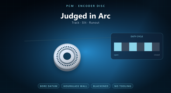
etched code wheel accuracy
Photochemical machining for metal encoder disc is easy to describe and hard to hold: the pattern is a set of slots, and the part is judged in arc-minutes. A disc that measures perfectly in millimetres can still produce a signal with phase error, because what the encoder reads is the position of each edge around the circle, and a tenth of a millimetre at the outside of a small disc is already a large angle. This page is about that conversion — where the angle comes from, where it is lost, and how it is measured.
1. The Part Is Judged in Angle
An encoder disc is a circle divided into equal angles. The phototool draws the divisions; the encoder interpolates between the edges they produce.
That makes the natural unit of the part an angle, not a length. A slit width of 20 µm on a disc of 20 mm radius subtends about 3.4 arc-minutes; the same 20 µm on a disc of 40 mm radius subtends half that. The same drawing, scaled, is not the same part. A 40 mm disc and a 20 mm disc with the same slit width are different encoders, so a scaled copy of a good disc is not automatically a good disc.
Two consequences follow. The first is that a disc drawing should be dimensioned in angles or in arc length at a stated radius, not only in millimetres. The second is that a change of disc diameter is a change of specification even when the pattern is copied. A disc dimensioned in arc is also easier to inspect, because the inspector measures where the optics read.
2. The Tolerance Chain to an Arc
Four things move the edge away from where the drawing put it.
The artwork is the first: a phototool has its own positional error, and at a fine pitch that error is a fraction of an edge spacing.
The etch is the second: undercut widens the slit, and the widening is not perfectly uniform around the circle, so the edges drift relative to each other.
The bore is the third, and it is the largest. A supplier who quotes a concentricity without asking for the bore datum has not understood the part, and the artwork error is the one most often underestimated at a fine pitch. The disc is located by its bore, and the tracks are concentric to it. An eccentricity of a few microns at the bore becomes an angular error that varies sinusoidally once per revolution — the classic signature in a phase-error plot.
Mounting is the fourth: a disc that is clamped unevenly, or seated on a burr, tilts, and a tilted disc reads its tracks at a different radius. Each of the four is measured differently, and none of them shows up in a millimetre check of the outline.
3. Slit Width, Thickness and Duty Cycle
The duty cycle of the optical signal is the ratio of open to closed along the track, and it is set by the slit width rather than by the pitch.
A slit that etches wide makes the open part of the cycle longer and the closed part shorter. The encoder’s interpolation assumes a nominal duty cycle; when the duty cycle drifts, the interpolated position drifts with it. That is why a duty-cycle error looks like a position error and not like a size error. A duty cycle that is off by a few percent is enough to move the interpolated zero.
Thickness enters because a two-sided etch produces an hourglass rather than a cylinder. A thick disc has a narrower waist than its entry, so the effective slit at the optical plane is not the slit on the drawing. A thin disc keeps the two closer together, which is why fine tracks are etched in thin stock. A slit that is too narrow is also a slit the resist may not define at all.
The measurement face therefore belongs on the drawing, and the waist is usually the number that matters. The waist is also what a plug gauge would measure, if a plug gauge could be made that small.
4. Bore, Hub and Runout
The bore is the datum, and everything else is measured from it.
A reamed or etched bore has its own tolerance, and the disc’s concentricity is usually called out to the bore rather than to the rim. That is correct, because the encoder shaft locates on the bore.
A separate hub adds a second interface: Concentricity to the bore is right, and concentricity to the rim is wrong. A separate hub adds a second interface: the hub is pressed or bonded into the disc, and the eccentricity of that joint adds to the bore eccentricity. An integral hub removes the joint but moves the tolerance into the etch, which is a different capability.
Runout should be measured at the track radius, not at the rim, because the track is what the optics read. A disc with good rim runout and a wavy track is a disc with a bad signal. A bore that is round but offset gives a clean sinusoid, and a bore that is oval gives a second harmonic.
5. Blackening and the Edge
The optical edge is not only geometry; it is also contrast.
A bare stainless disc reflects as well as it blocks, so a blackening step is normal: black oxide, a blackening conversion coating, or a matte coating. The coating changes the edge slightly, so the optical dimension should be taken after it rather than before.
A blackened disc also handles better, A blackened disc photographs badly, which is a problem for the catalogue and nothing else. A blackened disc also handles better, because fingerprints and handling marks no longer matter — small consolation, but real on a part that is fitted by hand.
Where the disc is used in reflection rather than transmission, the requirement inverts: A coating that is uneven around the disc adds its own once-per-revolution error. Where the disc is used in reflection rather than transmission, the requirement inverts: the reflective zone has to be bright and the rest matte, and that is usually a plated or polished band against a blackened background.
6. How the Disc Is Measured
Three measurement routes are used, and they answer different questions.
An optical measuring machine or a vision system measures the pattern in two dimensions: slit width, pitch and track position relative to the bore. It is the right tool for the drawing dimensions, and it is blind to the encoder.
A rotary fixture with a probe or a camera measures the disc as a turned part: runout at the track radius, and concentricity, by rotating the disc about its bore. That is the measurement that corresponds to how the disc will be used.
A functional test mounts the disc in an encoder and reads the waveform: duty cycle, amplitude and phase error. It is the only test that reports what the customer will feel, and it needs a known-good encoder head to mean anything. The three routes differ widely in cost, so a quote should say which one it includes.
A supplier who can only do the first has measured the drawing; a supplier who can do the third has measured the part. A rotary fixture also needs a bore clean enough to locate on, which is a handling requirement as much as a metrology one.
7. Batch Consistency
An encoder disc is bought in tens or hundreds, and the interesting question is whether the tenth batch matches the first. A repeat order that moves slightly forces a re-qualification, which is the hidden cost of a loose bore callout.
Because the pattern is imaged rather than cut, the batch-to-batch variation comes from the phototool, the resist, the etch bath and the bore. The first two are stable across a run; the bath drifts and is controlled; the bore is a separate operation and is where batch variation usually enters.
That is why a reorder should state the bore and the concentricity, not only the pattern, and why a first article from a new lot is worth measuring at the track rather than at the rim. A new lot is also where the phototool may be re-made, so the first article should be compared to the original, not to the last shipment.
8. Order Notes
An order should state the alloy and thickness, the pattern with track radii, pitches and slit widths, the measurement face, the bore with its tolerance and its datum role, the concentricity and runout limits and where they are measured, the blackening or reflective finish, and the packing.
It should also state the functional requirement: what duty cycle or phase error the encoder can tolerate. That number is what the supplier is really being asked to hold, and without it the dimensional callouts are a guess at what matters. With it written down, the dimensional callouts have a basis for trade-off.
The recurring mistakes are a pattern dimensioned only in millimetres with no radius, The optical face should also be marked, because a disc fitted upside down is a disc that has to be removed. The recurring mistakes are a pattern dimensioned only in millimetres with no radius, a concentricity callout with no datum, a runout measured at the rim, an optical dimension taken before blackening, and a drawing that never says which face is the optical one.
