

etched microchannel
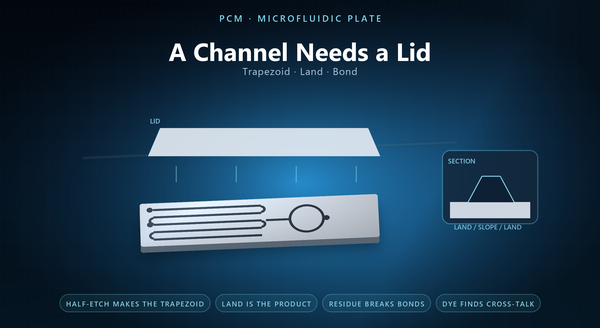
Photochemical machining for microfluidic plate is often described as making channels, and that description misses half the part. A microfluidic plate is a channel plus a lid: the etched plate is one half of a closed conduit, and the surface that has to bond to the lid is as much a designed feature as the channel itself. A plate with a beautiful channel and a rough bond land leaks, and a leaking plate is not a microfluidic device.
1. A Channel Plus a Lid
The etched plate is open. It becomes a conduit only when something closes it.
That closure is where most of the manufacturing risk sits. The channel defines the flow; the bond defines whether the flow stays where it was designed to go. A bond that is incomplete at one land, or that sags into a channel, changes the device more than a channel that is 10 percent wide.
The lid is usually the second plate, etched or plain, and its flatness matters as much as the channel plate’s. The useful framing is that The useful framing is that the etched plate has two surfaces to design: the channel floor and the bond land, and they have different requirements. A device is only as good as its worst land, and the land is the surface nobody photographs.
2. The Channel a Half-Etch Produces
A channel is usually made by half-etching from one face, not by etching through.
Etching from one face produces a channel with sloped walls and a flat floor: the etchant works down and sideways at once, so the opening at the surface is wider than the floor. The cross-section is a trapezoid.
A through-etched channel is a slot rather than a conduit, and cannot hold a flow without a lid on each side. Etching from both faces produces a symmetric profile Etching from both faces produces a symmetric profile with a wider middle — which for a channel means a cavity that is narrowest at the surface, which is not what a microfluidic channel usually wants.
That is why a channel is almost always a one-sided feature, and why the resist has to stay on the opposite face for the whole etch. A one-sided etch also leaves the opposite face untouched, which is convenient because that face is often the bond face and its finish has to survive.
3. Width, Depth and the Slope
Three numbers are coupled in an etched channel: the surface width, the floor width and the depth. Two of them can be specified and the third follows.
The slope of the wall is set by the etch behaviour, and the practical consequence is that a deep channel is a wide channel at the surface. A design that needs a narrow, deep channel is a design that may need a different process, or a different material, or a two-plate stack.
A drawing that gives a depth tolerance without the width tolerance has given half a specification. The floor width is the number that governs the flow in most low-Reynolds devices, The floor width is the number that governs the flow in most low-Reynolds devices, because it is the dimension the fluid actually sees between the walls. The surface width is the number that governs the resist image and the bond land.
A half-etch is a time-controlled feature, so the depth drifts with the bath before it drifts with the artwork. Writing only one width on a drawing is the most common microfluidic DFM error, Writing only one width on a drawing is the most common microfluidic DFM error, because the two differ by the wall slope over the depth. A wide, shallow channel is easy; a narrow, deep one is the geometry that separates processes, and it is worth knowing which one the design really is before quoting.
4. The Bond Land Is the Product
The bond land is the flat metal between channels, and it is the feature that decides whether the plate works.
Three properties matter. Its width has to be enough for the bonding method: a thermal bond needs more land than an adhesive, and a laser weld needs less again. Its flatness has to be good enough that the lid closes on it everywhere at once. And its roughness has to suit the bond: a very smooth land is good for diffusion bonding and can be bad for an adhesive that needs a key.
An etched land is usually flatter than a machined one because no tool force is applied, which is one of etching’s real advantages for this part. A land with a burr is a land that will not seal, and a land that has been handled after etching is a land with an unknown finish. A land that is too wide wastes area and adds dead volume at a channel edge, and a land’s flatness is measured on the bond face rather than the channel face. The land’s edge, where it meets the channel, is the feature that a bond has to seal over.
5. Four Bonding Routes
Four routes are common, and each one constrains the etch.
Thermal diffusion bonding joins two plates by heating them under pressure until the surfaces interdiffuse. It needs clean, flat, low-roughness lands and it is intolerant of any residue from the etch.
A thermal bond needs a furnace and a fixture, which is why it is chosen for a programme rather than a prototype. Laser welding is a local melt: Laser welding is a local melt: it needs land width for the weld bead and it puts local heat into a thin plate, which is a distortion risk near a channel.
Adhesive bonding is the most forgiving on land width and the least forgiving on cleanliness; it also risks wicking into a channel and changing its cross-section.
A gasket or an O-ring is a mechanical seal: it needs a land wide enough to seat, and a groove if the gasket has to be located, which is a second half-etch. A bonding method chosen before the land width is fixed is a method that will be changed after the first leak test.
6. Ports, Vias and Registration
A port etched through in the same step as the channels avoids a second registration, and a via that has to pass a fluid also has to drain. A plate has features that are not channels, and they have their own rules.
An inlet port is a through-hole, etched from both faces or drilled; its alignment to the channel matters more than its own tolerance, because a misaligned port creates a dead volume.
A via between layers has to be registered to the channel on both plates, which is why the two plates are usually etched from the same artwork set with the same registration marks.
The registration marks themselves are etched features, and they should be through-features so that an optical aligner can see them from either side. A plate pair etched from different artwork sets is a plate pair with a registration problem built in.
7. Proving It
Three tests prove a microfluidic plate, and they are not interchangeable.
A leak test pressurises the sealed channel with a gas or a liquid and looks for a rate of loss. It proves the bond.
A burst test on a prototype is worth more than a leak test on a hundred parts. A burst test raises the pressure until the bond fails, A burst test raises the pressure until the bond fails, which gives the margin rather than the pass.
A cross-section, cut and imaged, proves the channel geometry after bonding, which is the only way to see whether the adhesive has wicked or the bond has sagged.
A flow test with a dye proves the channel is continuous and that two channels are not connected, which is the failure that a leak test cannot see. A cross-section is also the only way to confirm the wall slope that the drawing assumed, which makes it a check on the drawing as much as on the part.
8. What the Drawing Should Say
A drawing for an etched microfluidic plate should state the alloy and thickness, the channel surface width, floor width and depth with the measurement basis, the land width and its flatness, the surface finish on the bond face, the port and via positions with their registration, the bonding method the plate is designed for, and the test that proves it.
It should also state which face is the bond face, because polishing or handling that changes it changes the bond.
A drawing that names the bond method lets the etcher choose the finish intelligently. The recurring mistakes are a channel specified by one width only, The recurring mistakes are a channel specified by one width only, A plate proved by one test is a plate proved against one failure mode. The recurring mistakes are a channel specified by one width only, a land too narrow for the chosen bonding method, an etch residue left for the bonder to remove, a port tolerance specified without its alignment, and a plate proved by a leak test alone.
